Disassembly
2 - 14 Removing and Installing the Processor
2.Disassembly
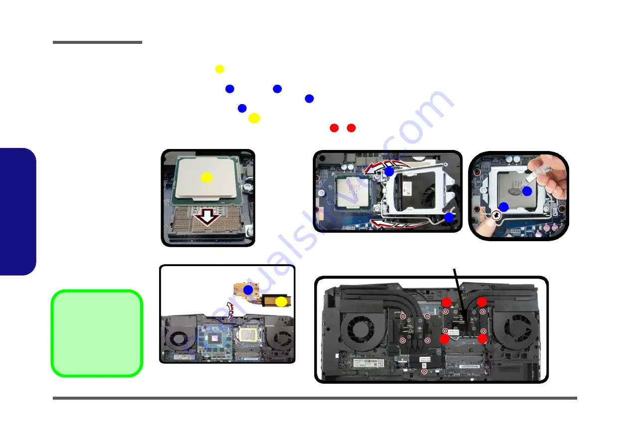
Processor Installation Procedure
1.
Insert the CPU
; pay careful attention to the pin alignment (
), it will fit only one way (DO NOT FORCE
IT!).
2.
Move the bracket
and latch
fully in the direction indicated to lock the CPU.
3.
Apply the whole tube of thermal grease
to the top of the CPU as shown (
).
4.
Remove the sticker
) from the heat sink unit (if it is a new unit).
5.
Insert the heat sink unit
as indicated in
.
6.
Tighten the CPU heat sink screws in the order
-
(the order as indicated on the label and
).
7.
Replace the CPU fan, component bay cover and tighten the screws (
A
B
C
D
E
F
1
4
b.
c.
d.
C
a.
E
F
1
4
2
Note
:
Tighten the screws in the order 1-2-3-4 as indicated.
3
A
B
D
C
Figure 10
Processor
Installation
a. Insert the CPU.
b. Move the latch and
bracket fully in the direc-
tion indicated to lock the
CPU. Apply thermal
grease.
c. Remove the sticker from
the heat sink unit and in-
sert the heat sink.
d. Tighten the screws.
A. CPU
F. Heat Sink
•
4 Screws
Summary of Contents for P775TM
Page 1: ...P775TM G P775TM1 G ...
Page 2: ......
Page 3: ...Preface I Preface Notebook Computer P775TM G P775TM1 G Service Manual ...
Page 24: ...Introduction 1 12 1 Introduction ...
Page 48: ...Disassembly 2 24 2 Disassembly ...
Page 51: ...Part Lists Top A 3 A Part Lists Top Figure A 1 Top ...
Page 52: ...Part Lists A 4 Bottom A Part Lists Bottom Figure A 2 Bottom ...
Page 53: ...Part Lists LCD LG AU A 5 A Part Lists LCD LG AU Figure A 3 LCD LG AU ...
Page 54: ...Part Lists A 6 LCD AU A Part Lists LCD AU Figure A 4 LCD AU ...
Page 55: ...Part Lists MB A 7 A Part Lists MB Figure A 5 MB ...
Page 56: ...Part Lists A 8 HDD A Part Lists HDD Figure A 6 HDD ...
Page 57: ...Part Lists VGA G1 G3 A 9 A Part Lists VGA G1 G3 Figure A 7 VGA G1 G3 ...
Page 58: ...Part Lists A 10 VGA G2 A Part Lists VGA G2 Figure A 8 VGA G2 ...


