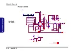
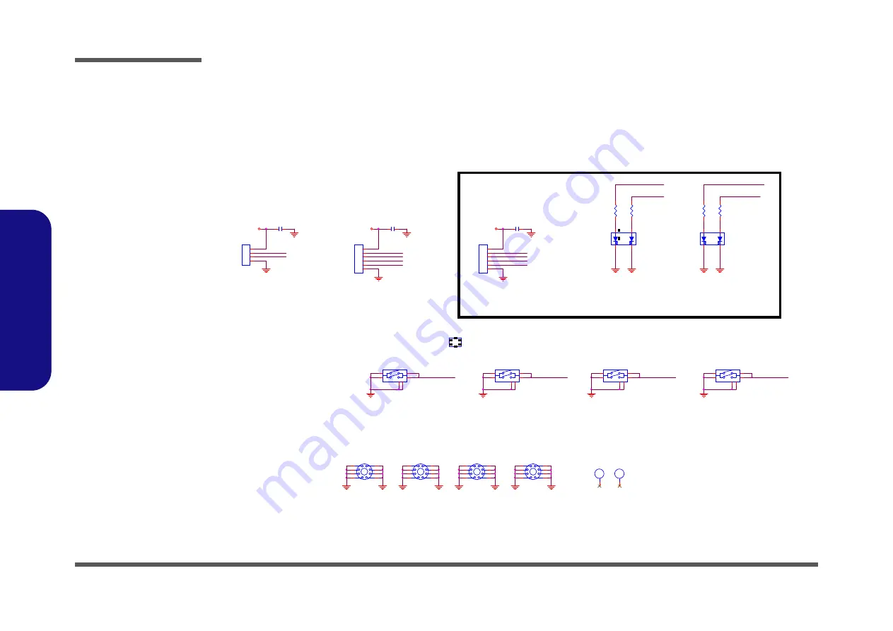
background image

Schematic  Diagrams

B - 40   Click Board 

B.Schematic Diagrams
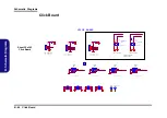
Click Board

C LED_BAT_F ULL
C LED_BAT_CHG

C LED_PWR
C LED_ACIN

CLED _BAT_F ULL

6-20-94A50-104

6-21-91A20-106

6-21-91A20-106

6-21-91A00-106

6-21-91A00-106

6-53-3050B-042

6-53-3050B-042

6-53-3050B-042

6-20-94A70-104

6-20-94AA0-104

1

6-53-3050B-042

BAT LED

POWER ON 

LED

2

CLED_ACIN

6-52-55002-04E

6-52-55002-042

CLED _BAT_CH G

C H6
H O-165X94_5NP

CH5
C95D95

CJ_TP3

*85201-06051

1
2
3
4
5
6

1

CH1

MTH237D91

2
3
4
5

6

7

8

9

C R3

*220_04

CC2

*0.1u_16V_Y 5V_04

CSW2
TJG-533-S-T/R

3

1

4

2

5

6

CC1

0.1u_16V_Y 5V_04

CR1

* 220_04

CLICK BOARD

CSW 3
*TJG-533-S-T/R

3

1

4

2

5

6

CSW4
*TJG-533-S-T/R

3

1

4

2

5

6

CC3

*0.1u_16V_Y 5V_04

1

CH4

MTH237D91

2
3
4
5

6

7

8

9

CJ_TP2

85201-06051

1
2
3
4
5
6

CJ_TP1

85201-04051

1
2
3
4

CSW1
TJG-533-S-T/R

3

1

4

2

5

6

SG

Y

CD26

*KPB-3025Y SGC

1

3

2

4

CR4

*220_04

1

CH 2

MTH 237D91

2
3
4
5

6

7

8

9

SG

Y

CD27

*KPB-3025Y SGC

1

3

2

4

CR2

*220_04

C GND

CGN D

1

CH3

MTH237D91

2
3
4
5

6

7

8

9

CGND

CGND

CGND

CGND

CGND

CGN D

CGND

CGND

CGND

C5VS

CGND

CGND

CGND

CGND

CGND

CVDD 3

CGN D

CGN D

C5VS

CGND

CGND

CGND

CGND

CTPBUTTON_R

CTPBUTTON_L

CTPBUTTON_R

CTPBUTTON_L

RIGHT

 KEY

LIFT

KEY

LIFT

KEY

1

RIGHT

 KEY

CSW1~4

3

4

6-52-55002-04E

6-52-55002-042

2

CTP_DATA

CTP_CLK

CTPBUTTON_R

CTP_CLK

CTP_DATA

CTPBUTTON_L

CLED_PWR

W240HU  ¤£¤W¥ó

W250HU  ¤W¥ó

Sheet 39 of 43

Click Board

Summary of Contents for W251EUQ

Page 1: ...W251EUQ W253EUQ W255EU W258EUQ ...

Page 2: ......

Page 3: ...Preface I Preface Notebook Computer W251EUQ W253EUQ W255EU W258EUQ Service Manual ...

Page 4: ...or in part be reproduced translated transmitted or reduced to any machine readable form without prior consent from the vendor manufacturer or creators of this publica tion except for copies kept by the user for backup purposes Brand and product names mentioned in this publication may or may not be copyrights and or registered trademarks of their respective companies They are mentioned for identifi...

Page 5: ...d or upgrading components of the W251EUQ W253EUQ W255EU W258EUQ series notebook PC The following information is included Chapter 1 Introduction provides general information about the location of system elements and their specifications Chapter 2 Disassembly provides step by step instructions for disassembling parts and subsystems and how to upgrade elements of the system Appendix A Part Lists Appe...

Page 6: ...port a gas leak in the vicinity of the leak 4 Use only the power cord and batteries indicated in this manual Do not dispose of batteries in a fire They may explode Check with local codes for possible special disposal instructions 5 This product is intended to be supplied by a Listed Power Unit with an AC Input of 100 240V 50 60Hz DC Output of 19V 3 42A or 18 5V 3 5A 65W minimum AC DC Adapter CAUTI...

Page 7: ... down properly and don t forget to save your work Remember to periodically save your data as data may be lost if the battery is depleted Do not expose the computer to any shock or vibration Do not place it on an unstable surface Do not place anything heavy on the computer Do not expose it to excessive heat or direct sunlight Do not leave it in a place where foreign matter or mois ture may affect t...

Page 8: ... its purpose If you do not have access to a compatible outlet have a qualified electrician install one When you want to unplug the power cord be sure to disconnect it by the plug head not by its wire Make sure the socket and any extension cord s you use can support the total current load of all the connected devices Before cleaning the computer make sure it is disconnected from any external power ...

Page 9: ...ur hands or metal objects Battery Guidelines The following can also apply to any backup batteries you may have If you do not use the battery for an extended period then remove the battery from the computer for storage Before removing the battery for storage charge it to 60 70 Check stored batteries at least every 3 months and charge them to 60 70 Battery Disposal The product that you have purchase...

Page 10: ...rals you want to use with the computer e g keyboard and mouse to their ports 5 Attach the AC DC adapter to the DC In jack at the rear of the computer then plug the AC power cord into an outlet and connect the AC power cord to the AC DC adapter 6 Use one hand to raise the lid LCD to a comfortable viewing angle do not exceed 130 degrees use the other hand as illustrated in Figure 1 to support the ba...

Page 11: ...Removing the Wireless LAN Module 2 15 Removing the Keyboard 2 16 Part Lists A 1 Part List Illustration Location A 2 Top W251EUQ A 3 Top W255EU A 4 Top W258EUQ A 5 Top W253EUQ A 6 Bottom W251EUQ W255EU W258EUQ A 7 Bottom W253EUQ A 8 SATA BLU RAY COMBO W251EUQ W255EU W258EUQ A 9 SATA BLU RAY COMBO W253EUQ A 10 DVD DUAL W251EUQ W253EUQ W255EU W258EUQ A 11 DVD DUAL W253EUQ A 12 LCD W251EUQ W253EUQ W25...

Page 12: ...B 32 VDD3 VDD5 B 33 Power 1 5V 0 75V 1 8VS B 34 Power 1 05VS B 35 Power 0 85VS B 36 Power V Core1 B 37 Power V Core2 B 38 Charger AC In B 39 Click Board B 40 Audio Board USB B 41 Power Switch LID Board B 42 External ODD Board B 43 Updating the FLASH ROM BIOS C 1 Download the BIOS C 1 Unzip the downloaded files to a bootable CD DVD or USB Flash drive C 1 Set the computer to boot from the external d...

Page 13: ...l is shipped with the computer Operating systems e g Window 7 etc have their own manuals as do application softwares e g word processing and database programs If you have questions about those programs you should consult those manuals The W251EUQ W253EUQ W255EU W258EUQ series notebook is designed to be upgradeable See Disassembly on page 2 1 for a detailed description of the upgrade procedures for...

Page 14: ...GHz i5 2410M 2 30GHz 3MB L3 Cache 32nm DDR3 1333MHz TDP 35W Intel Core i3 Processor i3 2370M 2 40GHz i3 2350M 2 30GHz i3 2330M 2 20GHz i3 2310M 2 10GHz 3MB L3 Cache 32nm DDR3 1333MHz TDP 35W Intel Pentium Processor B970 2 30GHz B960 2 20GHz B950 2 10GHz B940 2 00GHz 2MB L3 Cache 32nm DDR3 1333MHz TDP 35W Intel Celeron Processor B840 1 90GHz B815 1 60GHz B810 1 60GHz B800 1 50GHz 2MB L3 Cache 32nm ...

Page 15: ...2 for 3 75G HSPA Module Communication Built In Gigabit Ethernet LAN Factory Option 300K 1 3M Pixel USB PC Camera Mod ule Factory Option 3 75G HSPA Mini Card Module WLAN Bluetooth Half Mini Card Modules Factory Option Intel Centrino Wireless N 2230 Wireless LAN 802 11b g n Bluetooth 4 0 Factory Option Intel Centrino Wireless N 135 Wire less LAN 802 11b g n Bluetooth 4 0 Factory Option Third Party W...

Page 16: ...uction External Locator Top View with LCD Panel Open Figure 1 Top View 1 PC Camera Optional 2 LCD 3 Power Button 4 LED Status Indicators 5 Keyboard 6 Built In Microphone Note that the microphone location is dependent upon your model design 7 Touchpad Buttons 5 3 4 6 1 7 2 ...

Page 17: ...troduction External Locator Front Right Side Views Figure 2 Front View 1 LED Power Indicator Figure 3 Right Side View 1 Microphone In Jack 2 Headphone Out Jack 3 USB 2 0 Port 4 Optical Device Drive Bay 5 Emergency Eject Hole FRONT VIEW 1 RIGHT SIDE VIEW 1 2 3 5 4 ...

Page 18: ...xternal Locator Left Side Rear View Figure 4 Left Side View 1 DC In Jack 2 External Monitor Port 3 RJ 45 LAN Jack 4 HDMI Out Port 5 USB 3 0 Ports 6 Vent 7 Multi in 1 Card Reader LEFT SIDE VIEW 1 2 3 4 5 6 5 7 Figure 5 Rear View 1 Security Lock Slot 2 Battery REAR VIEW 1 2 ...

Page 19: ...Bottom View Figure 6 Bottom View 1 Battery 2 Component Bay Cover 3 Vent 4 Hard Disk Bay Cover 5 3 75G USIM Card Cover Optional 6 Speakers Overheating To prevent your com puter from overhea ting make sure no thing blocks any vent while the computer is in use 2 3 1 4 3 3 6 6 3 3 5 ...

Page 20: ...Introduction 1 8 Mainboard Overview Top Key Parts 1 Introduction Mainboard Overview Top Key Parts Figure 7 Mainboard Top Key Parts 1 ITE 8518E 2 AZALIA Codec 2 1 ...

Page 21: ... 1 Memory Slots DDR3 SO DIMM 2 Accelerated Processing Unit 3 Intel NM10 PCH 4 CMOS Battery 5 Mini Card Connector WLAN Module 6 Card Reader Socket Introduction Mainboard Overview Bottom Key Parts 1 9 1 Introduction Mainboard Overview Bottom Key Parts ...

Page 22: ...rd Overview Top Connectors Figure 9 Mainboard Top Connectors 1 HDMI Out Port 2 USB Port 3 0 3 Speaker Cable Connector 4 Microphone Cable Connector 5 Audio Board Connector 6 TouchPad Cable Connector 1 7 Keyboard Cable Connector 8 Switch Board Cable Connector 1 2 8 2 3 4 6 7 5 ...

Page 23: ...n Mainboard Overview Bottom Connectors Figure 10 Mainboard Bottom Connectors 1 Battery Connector 2 ODD Connector 3 HDD Connector 4 CPU Fan Cable Connector 5 RJ 45 LAN Jack 6 External Monitor Port 7 DC In Jack 8 CCD Cable Connector 9 LCD Cable Connector 1 2 4 5 6 7 8 9 3 ...

Page 24: ...Introduction 1 12 1 Introduction ...

Page 25: ...e the disassembly process easier each section may have a box in the page margin Information contained under the figure will give a synopsis of the sequence of procedures involved in the disassembly procedure A box with a lists the relevant parts you will have after the disassembly process is complete Note The parts listed will be for the dis assembly procedure listed ONLY and not any previous disa...

Page 26: ...c ing the connection make sure the connector is oriented in the same way The pin1 side is usually not indicated Pressure sockets for multi wire connectors To release this connector type grasp it at its head and gently rock it from side to side as you pull it out Do not pull on the wires themselves When replacing the connection do not try to force it The socket only fits one way Pressure sockets fo...

Page 27: ... Do not pull on the wire 6 Peripherals Turn off and detach any peripherals 7 Beware of static discharge ICs such as the CPU and main support chips are vulnerable to static electricity Before handling any part in the computer discharge any static electricity inside the computer When handling a printed circuit board do not use gloves or other materials which allow static electricity buildup We sugge...

Page 28: ...evice 1 Remove the battery page 2 5 2 Remove the Optical device page 2 8 To remove the System Memory 1 Remove the battery page 2 5 2 Remove the system memory page 2 9 To remove and install a Processor 1 Remove the battery page 2 5 2 Remove the processor page 2 11 3 Install the processor page 2 13 To remove the 3 75G Module 1 Remove the battery page 2 5 2 Remove the 3 75G module page 2 14 To remove...

Page 29: ...ide the latch in the direction of the arrow Figure 1a 3 Slide the latch in the direction of the arrow and hold it in place Figure 1a 4 Slide the battery in the direction of the arrow Figure 1b 1 2 6 3 4 Figure 1 Battery Removal a Slide the latch and hold it in place b Slide the battery in the di rection of the arrow 1 a b 3 2 4 ...

Page 30: ...ess Figure 2 HDD Assembly Removal a Locate the HDD bay cover and remove the screws 2 Screws 1 Turn off the computer and remove the battery page 2 5 2 Locate the hard disk bay cover and remove screws Figure 2a 1 2 2 1 a HDD System Warning New HDD s are blank Before you begin make sure You have backed up any data you want to keep from your old HDD You have all the CD ROMs and FDDs required to instal...

Page 31: ...r cover from the hard disk Figure 3e 7 Reverse the process to install a new hard disk do not forget to replace all the screws and covers 6 3 4 6 5 6 7 10 11 12 4 b c 6 9 d 3 e 11 8 7 12 5 10 3 HDD Bay Cover 5 HDD Assembly 11 Mylar Cover 12 HDD 4 Screws Figure 3 HDD Assembly Removal cont d b Remove the HDD bay cover c Grip the tab and slide the HDD assembly in the di rection of the arrow d Lift the...

Page 32: ...off the computer remove the battery page 2 5 and hard disk page 2 6 2 Remove the screw at point Figure 4a 3 Use a screwdriver to carefully push out the optical device at point Figure 4b 4 Insert the new device and carefully slide it into the computer the device only fits one way DO NOT FORCE IT The screw holes should line up 5 Restart the computer to allow it to automatically detect the new device...

Page 33: ... Small Outline Dual In line Memory Modules SO DIMM supporting DDRIII DDR3 Up to 1066 1333 MHz The main memory can be expanded up to 8GB The SO DIMM modules sup ported are 1024MB and 2048MB DDRIII Modules The total memory size is automatically detected by the POST rou tine once you turn on your computer Memory Upgrade Process 5 Screws 1 Turn off the computer turn it over and remove the battery page...

Page 34: ...ule in and down towards the mainboard until the slot levers click into place to secure the module 11 Replace the bay cover Figure 6e and the screws make sure you reconnect the fan cable before screwing down the bay cover 12 Restart the computer to allow the BIOS to register the new memory configuration as it starts up Figure 6 RAM Module Removal cont d c Pull the release lat ches d Remove the modu...

Page 35: ...be visible at point Figure 7a 3 Loosen the CPU heat sink screws in the order the reverse order as indicated on the label Figure 7a 4 Grip the heat sink tab and carefully lift the heat sink up and off the computer Figure 7b A 3 2 1 7 Figure 7 Processor Removal a The CPU heat sink will be visible at point Remove the screws from the CPU heatsink b Grip the heat sink tab and carefully lift the heat si...

Page 36: ...rocess to install a new CPU 8 When re inserting the CPU pay careful attention to the pin alignment it will fit only one way DO NOT FORCE IT 5 6 Figure 8 Processor Removal cont d c Turn the release latch to unlock the CPU d Lift the CPU out of the socket c d Caution The heat sink and CPU area in general contains parts which are subject to high temperatures Allow the area time to cool before remov i...

Page 37: ...nk as indicated in Figure 9d 4 Tighten the CPU heat sink screws in the order r the order as indicated on the label and Figure 9d 5 Replace the component bay cover don t forget to replace the fan cable and tighten the screws page 2 9 A B C D 1 2 3 b B a D Note Tighten the screws in the order as indi cated on the label C A c d 1 2 3 Figure 9 Processor Installation a Insert the CPU b Turn the release...

Page 38: ... 3 75G mod ule Note Make sure you reconnect the antenna cable to socket 1 Turn off the computer turn it over and remove the battery page 2 5 and the component bay cover page 2 9 2 Carefully disconnect the cable then remove the screw from the module socket 3 The 3 75G module Figure 10b will pop up and you can remove it from the computer Figure 10c 1 2 4 3 b a d 1 2 3 c 3 3 75G Module 1 Screw ...

Page 39: ...nect the antenna cable to the 1 2 socket Figure 11b 1 Turn off the computer turn it over and remove the battery page 2 5 and the component bay cover page 2 9 2 The Wireless LAN module will be visible at point on the mainboard Figure 11a 3 Carefully disconnect the cables and then remove the screw Figure 11b 4 The Wireless LAN module Figure 11c will pop up and you can remove it from the computer 1 2...

Page 40: ...nts to unsnap the LED cover module you may need to use the Eject Pin Tool to do this Figure 12a 3 Remove the LED cover module and screws from the keyboard Figure 12b 4 Carefully lift the keyboard up being careful not to bend the keyboard ribbon cable Disconnect the keyboard ribbon cable from the locking collar socket Figure 12c 5 Carefully lift up the keyboard Figure 12d off the computer 1 2 3 4 4...

Page 41: ...art numbers Your organization may use a different system so be sure to cross check any relevant documentation Note Some assemblies may have parts in common especially screws However the part lists DO NOT indicate the total number of duplicated parts used Note Be sure to check any update notices The parts shown in these illustrations are appropriate for the system at the time of publication Over th...

Page 42: ...to find the appropriate part list illustration Table A 1 Part List Illustration Location Part W251EUQ W255EU W258EUQ W253EUQ Top page A 3 page A 4 page A 5 page A 6 Bottom page A 7 page A 8 SATA BLU RAY COMBO page A 9 page A 10 DVD Dual Drive page A 11 page A 12 LCD page A 13 page A 14 ...

Page 43: ...Top W251EUQ A 3 A Part Lists Top W251EUQ 非耐落 灰色 尚盟 Figure A 1 Top W251EUQ ...

Page 44: ...A 4 Top W255EU A Part Lists Top W255EU 灰色 尚盟 非耐落 Figure A 2 Top W255EU ...

Page 45: ...Top W258EUQ A 5 A Part Lists Top W258EUQ 非耐落 非耐落 灰色 尚盟 Figure A 1 Top W258EUQ ...

Page 46: ...A 6 Top W253EUQ A Part Lists Top W253EUQ Figure A 1 Top W253EUQ ...

Page 47: ...Bottom W251EUQ W255EU W258EUQ A 7 A Part Lists Bottom W251EUQ W255EU W258EUQ Figure A 2 Bottom W251EUQ W255EU W258EUQ ...

Page 48: ...A 8 Bottom W253EUQ A Part Lists Bottom W253EUQ Figure A 3 Bottom W253EUQ ...

Page 49: ...SATA BLU RAY COMBO W251EUQ W255EU W258EUQ A 9 A Part Lists SATA BLU RAY COMBO W251EUQ W255EU W258EUQ 非耐落 志精 Figure A 4 SATA BLU RAY COMBO W251EUQ W255EU W258EUQ ...

Page 50: ...A 10 SATA BLU RAY COMBO W253EUQ A Part Lists SATA BLU RAY COMBO W253EUQ 非耐落 志精 Figure A 5 SATA BLU RAY COMBO W253EUQ ...

Page 51: ...DVD DUAL W251EUQ W253EUQ W255EU W258EUQ A 11 A Part Lists DVD DUAL W251EUQ W253EUQ W255EU W258EUQ Figure A 6 DVD DUAL W251EUQ W253EUQ W255EU W258EUQ 非耐落 志精 ...

Page 52: ...A 12 DVD DUAL W253EUQ A Part Lists DVD DUAL W253EUQ Figure A 7 DVD DUAL W253EUQ 非耐落 志精 ...

Page 53: ...LCD W251EUQ W253EUQ W255EU W258EUQ A 13 A Part Lists LCD W251EUQ W253EUQ W255EU W258EUQ 頭厚 非耐落 Figure A 8 LCD W251EUQ W253EUQ W255EU W258EUQ ...

Page 54: ...A 14 LCD W253EUQ A Part Lists LCD W253EUQ Figure A 9 LCD W253EUQ ...

Page 55: ...B 7 CCD 3G TPM Page B 24 Audio Board USB Page B 41 Ivy Bridge Processor 6 7 Page B 8 Card Reader LAN RTL8411 Page B 25 Power Switch LID Board Page B 42 Ivy Bridge Processor 7 7 Page B 9 LAN RTL8411 SATA HDD ODD Page B 26 External ODD Board Page B 43 DDR3 SO DIMM_0 Page B 10 USB 3 0 TI TUSB7320 Page B 27 Power Sequence Page B 44 DDR3 SO DIMM_1 Page B 11 KBC ITE IT8518 Page B 28 LVDS Inverter Page B...

Page 56: ...Codec EC 0 5 11 SOCKET 5V 3V 5VS 3VS 1 5VS 1 5VS_CPU 15 SHEET 22 RJ 45 VDD3 VDD5 DMI 4 32 768 KHz W83L771AWG Realtek 6 71 W24ES D03 SATA I II 3 0Gb s ALC269 VT1802P Co layout 1333 1600 MHz DDR3 1 5V 14 14 1 6mm 33 MHz THERMAL SENSOR 100 MHz POWER SWITCH BOARD 810602 1703 SMART FAN USB5 PROCESSOR 37 5 37 5 mm RTL8411 PantherPoint Platform Controller Hub PCH 25x25x0 6 mm 989 Balls FCBGA rPGA989 988 ...

Page 57: ...3 H35 PEG_RX 4 H32 PEG_RX 5 G34 PEG_RX 6 G31 PEG_RX 7 F33 PEG_RX 8 F30 PEG_RX 9 E35 PEG_RX 10 E33 PEG_RX 11 F32 PEG_RX 12 D34 PEG_RX 13 E31 PEG_RX 14 C33 PEG_RX 15 B32 PEG_TX 0 M29 PEG_TX 1 M32 PEG_TX 2 M31 PEG_TX 3 L32 PEG_TX 4 L29 PEG_TX 5 K31 PEG_TX 6 K28 PEG_TX 7 J30 PEG_TX 8 J28 PEG_TX 9 H29 PEG_TX 10 G27 PEG_TX 11 E29 PEG_TX 12 F27 PEG_TX 13 D28 PEG_TX 14 F26 PEG_TX 15 E25 PEG_TX 0 M28 PEG_T...

Page 58: ...cessor Pullups Pull downs TRACE WIDTH 10MIL LENGTH 500MILS 3 3VS BUF_CPU_RST DDR3 Compensation Signals SM_RCOMP_2 SM_RCOMP_1 SM_RCOMP_0 C96 68p_50V_NPO_04 VDDPWRGOOD_R XDP_TRST XDP_TCLK PLT_RST 17 23 XDP_TMS XDP_TDI_R CPUDRAMRST H_PROCHOT _D H_CATERR Buffered reset to CPU XDP_TDO_R XDP_PREQ H_THRMTRIP 18 H_SNB_IVB 18 R382 25 5_1 _04 R381 200_1 _04 R419 10mil_04 R412 10K_04 R413 140_1 _04 H_PECI 18...

Page 59: ... SB_DQ 39 AP2 SB_DQ 40 AP5 SB_DQ 41 AN9 SB_DQ 42 AT5 SB_DQ 43 AT6 SB_DQ 44 AP6 SB_DQ 45 AN8 SB_DQ 46 AR6 SB_DQ 47 AR5 SB_DQ 48 AR9 SB_DQ 49 AJ11 SB_DQ 50 AT8 SB_DQ 51 AT9 SB_DQ 52 AH11 SB_DQ 53 AR8 SB_DQ 54 AJ12 SB_DQ 55 AH12 SB_DQ 56 AT11 SB_DQ 57 AN14 SB_DQ 58 AR14 SB_DQ 59 AT14 SB_DQ 60 AT12 SB_DQ 61 AN15 SB_DQ 62 AR15 SB_DQ 63 AT15 SB_CK 2 AB2 SB_CLK 2 AA2 SB_CKE 2 T9 SB_CK 3 AA1 SB_CLK 3 AB1 ...

Page 60: ...VCCIO30 C14 VCCIO31 C13 VCCIO_SENSE B10 VCCIO40 J23 VCORE_VCC_SENSE 36 C53 10u_6 3V_X5R_06 SVID Signals R86 130_1 _04 R408 75_1 _04 R89 54 9_1 _04 VTT_CPU H_CPU_SVIDDAT_R H_CPU_SVIDCLK H_CPU_SVIDALRT CAD Note H_CPU_SVIDALRT _R H_CPU_SVIDDAT_R Place the PU resistors close to CPU R85 20mil_04 R88 20mil_04 C417 220u_6 3V_6 3 6 3 4 2 PROCESSOR UNCORE POWER C72 10u_6 3V_X5R_06 C66 10u_6 3V_X5R_06 C62 1...

Page 61: ...S R119 1K_1 _04 R114 100K_1 _04 VREF_CH_B_DIMM 10 R117 1K_1 _04 1 5V SUSB 15 27 31 V_SM_VREF_CNT V_SM_VREF_CNT C400 330U_2 5V_D2_D R56 10K_04 POWER GRAPHICS DDR3 1 5V RAILS SENSE LINES 1 8V RAIL SA RAIL VREF MISC U34G PZ98827 364B 01F SM_VREF AL1 VSSAXG_SENSE AK34 VAXG_SENSE AK35 VAXG1 AT24 VAXG2 AT23 VAXG3 AT21 VAXG4 AT20 VAXG5 AT18 VAXG6 AT17 VAXG7 AR24 VAXG8 AR23 VAXG9 AR21 VAXG10 AR20 VAXG11 A...

Page 62: ...VSS132 AB32 VSS133 AB31 VSS134 AB30 VSS135 AB29 VSS136 AB28 VSS137 AB27 VSS138 AB26 VSS139 Y9 VSS140 Y8 VSS141 Y6 VSS142 Y5 VSS143 Y3 VSS144 Y2 VSS145 W35 VSS146 W34 VSS147 W33 VSS148 W32 VSS149 W31 VSS150 W30 VSS151 W29 VSS152 W28 VSS153 W27 VSS154 W26 VSS155 U9 VSS156 U8 VSS157 U6 VSS158 U5 VSS159 U3 VSS160 U2 VSS U34I PZ98827 364B 01F VSS161 T35 VSS162 T34 VSS163 T33 VSS164 T32 VSS165 T31 VSS16...

Page 63: ...PU_RSVD3 H_CPU_RSVD2 CFG7 CFG4 CFG2 CFG6 CFG0 CFG5 RESERVED CFG U34E PZ98827 364B 01F CFG 0 AK28 CFG 1 AK29 CFG 2 AL26 CFG 3 AL27 CFG 4 AK26 CFG 5 AL29 CFG 6 AL30 CFG 7 AM31 CFG 8 AM32 CFG 9 AM30 CFG 10 AM28 CFG 11 AM26 CFG 12 AN28 CFG 13 AN31 CFG 14 AN26 CFG 15 AM27 CFG 16 AK31 CFG 17 AN29 RSVD34 AM33 RSVD35 AJ27 RSVD38 J16 RSVD_NCTF42 AT34 RSVD39 H16 RSVD40 G16 RSVD_NCTF41 AR35 RSVD_NCTF43 AT33 ...

Page 64: ...DQ56 181 DQ57 183 DQ58 191 DQ59 193 DQ60 180 DQ61 182 DQ62 192 DQ63 194 BA0 109 BA1 108 RAS 110 WE 113 CAS 115 S0 114 S1 121 CKE0 73 CKE1 74 CK0 101 CK0 103 CK1 102 CK1 104 SDA 200 SCL 202 SA1 201 SA0 197 DM0 11 DM1 28 DM2 46 DM3 63 DM4 136 DM5 153 DM6 170 DM7 187 DQS0 12 DQS1 29 DQS2 47 DQS3 64 DQS4 137 DQS5 154 DQS6 171 DQS7 188 DQS0 10 DQS1 27 DQS2 45 DQS3 62 DQS4 135 DQS5 152 DQS6 169 DQS7 186...

Page 65: ...59 DQ26 67 DQ27 69 DQ28 56 DQ29 58 DQ30 68 DQ31 70 DQ32 129 DQ33 131 DQ34 141 DQ35 143 DQ36 130 DQ37 132 DQ38 140 DQ39 142 DQ40 147 DQ41 149 DQ42 157 DQ43 159 DQ44 146 DQ45 148 DQ46 158 DQ47 160 DQ48 163 DQ49 165 DQ50 175 DQ51 177 DQ52 164 DQ53 166 DQ54 174 DQ55 176 DQ56 181 DQ57 183 DQ58 191 DQ59 193 DQ60 180 DQ61 182 DQ62 192 DQ63 194 BA0 109 BA1 108 RAS 110 WE 113 CAS 115 S0 114 S1 121 CKE0 73 ...

Page 66: ...TN7002ZHS3 G D S Q47 MEP4435Q8 4 6 2 5 7 3 1 8 MUX_2N MUX_1N MUX_1P S D G Q59B L2N7002DW1T1G 5 3 4 2A LVDS L2N INV_BLON MUX_2P S D G Q59A L2N7002DW1T1G 2 6 1 P_DDC_DATA LVDS L2P BRIGHTNESS NB_ENAVDD P_DDC_CLK R653 10K_04 LVDS LCLKN 16 LVDS L0P 16 LVDS L0N 16 R652 220_06 LVDS LCLKP 16 3 3V NB_ENAVDD MUX_3P MUX_3N C640 0 22u_50V_Y5V_06 VLED R654 1M_04 NB_ENAVDD R655 100K_04 VIN C517 0 1u_50V_Y5V_06 ...

Page 67: ... 5 6 7 8 HDMIB_D0BP_M RN20 0_8P4R_04_SHORT 1 2 3 4 5 6 7 8 HDMIB_D0BN_M HDMIB_DATA2P HDMIB_D1BN HDMIB_D1BP HDMIB_D2BN HDMIB_D2BP HDMIB_DATA0P HDMIB_CLKBN HDMIB_CLKBP HDMIB_DATA1N HDMIB_DATA1P HDMIB_DATA2N RN23 0_8P4R_04_SHORT 1 2 3 4 5 6 7 8 HDMIB_DATA0N RN22 0_8P4R_04_SHORT 1 2 3 4 5 6 7 8 5VS W O level shift 3 3VS R665 680_04 R666 680_04 R663 680_04 R664 680_04 TMDS_DATA1 TMDS_DATA0 Q56 MTN7002Z...

Page 68: ... 51_04 HM70 Disable port 3 R459 100_1 _04 3 3V PCH_JTAG_TCK_BUF PCH_JTAG_TMS PCH_JTAG_TDO PCH_JTAG_TDI HDA_SYNC_L RTC IHDA SATA LPC SPI JTAG SATA 6G U37A Panther Point S A1 RTCX1 A20 RTCX2 C20 INTVRMEN C17 INTRUDER K22 HDA_BCLK N34 HDA_SYNC L34 HDA_RST K34 HDA_SDIN0 E34 HDA_SDIN1 G34 HDA_SDIN2 C34 HDA_SDO A36 SATALED P3 FWH0 LAD0 C38 FWH1 LAD1 A38 FWH2 LAD2 B37 FWH3 LAD3 C37 LDRQ1 GPIO23 K36 FWH4 ...

Page 69: ...CKS SMBUS Controller Link U37B Panther Point S A1 PERN1 BG34 PERP1 BJ34 PERN2 BE34 PERP2 BF34 PERN3 BG36 PERP3 BJ36 PERN4 BF36 PERP4 BE36 PERN5 BG37 PERP5 BH37 PERN6 BJ38 PERP6 BG38 PERN7 BG40 PERP7 BJ40 PERN8 BE38 PERP8 BC38 PETN1 AV32 PETP1 AU32 PETN2 BB32 PETP2 AY32 PETN3 AV34 PETP3 AU34 PETN4 AY34 PETP4 BB34 PETN5 AY36 PETP5 BB36 PETN6 AU36 PETP6 AV36 PETN7 AY40 PETP7 BB40 PETN8 AW38 PETP8 AY3...

Page 70: ...W16 PMSYNCH AP14 SLP_SUS G16 SLP_S3 F4 SLP_S4 H4 SLP_S5 GPIO63 D10 SYS_RESET K3 SYS_PWROK P12 PWRBTN E20 RI A10 WAKE B9 SUS_STAT GPIO61 G8 SUSCLK GPIO62 N14 ACPRESENT GPIO31 H20 BATLOW GPIO72 E10 PWROK L22 CLKRUN GPIO32 N3 SUSWARN SUSPWRDNACK GPIO30 K16 RSMRST C21 DRAMPWROK B13 SLP_LAN GPIO29 K14 APWROK L10 DPWROK E22 DMI2RBIAS BH21 SLP_A G10 DSWVRMEN A18 SUSACK C12 SYS_PWROK SLP_S5 R545 10K_04 R5...

Page 71: ...Interface CRT U37D Panther Point S A1 L_BKLTCTL P45 L_BKLTEN J47 L_CTRL_CLK T45 L_CTRL_DATA P39 L_DDC_CLK T40 L_DDC_DATA K47 L_VDD_EN M45 LVDSA_CLK AK39 LVDSA_CLK AK40 LVDSA_DATA 0 AN48 LVDSA_DATA 1 AM47 LVDSA_DATA 2 AK47 LVDSA_DATA 3 AJ48 LVDSA_DATA0 AN47 LVDSA_DATA1 AM49 LVDSA_DATA2 AK49 LVDSA_DATA3 AJ47 LVDSB_CLK AF40 LVDSB_CLK AF39 LVDSB_DATA 0 AH45 LVDSB_DATA 1 AH47 LVDSB_DATA 2 AF49 LVDSB_DA...

Page 72: ...RSVD26 AY5 RSVD27 BA2 RSVD28 AT12 RSVD29 BF3 PIRQA K40 PIRQB K38 PIRQC H38 PIRQD G38 REQ1 GPIO50 C46 REQ2 GPIO52 C44 REQ3 GPIO54 E40 GNT1 GPIO51 D47 GNT2 GPIO53 E42 GNT3 GPIO55 F46 PIRQE GPIO2 G42 PIRQF GPIO3 G40 PIRQG GPIO4 C42 PIRQH GPIO5 D44 USBP0N C24 USBP0P A24 USBP1N C25 USBP1P B25 USBP2N C26 USBP2P A26 USBP3N K28 USBP3P H28 USBP4N E28 USBP4P D28 USBP5N C28 USBP5P A28 USBP6N C29 USBP6P B29 U...

Page 73: ...4 BJ6 VSS_NCTF_25 C2 VSS_NCTF_26 C48 VSS_NCTF_27 D1 VSS_NCTF_28 D49 VSS_NCTF_29 E1 VSS_NCTF_30 E49 VSS_NCTF_31 F1 TS_VSS4 AK10 TS_VSS3 AH10 TS_VSS2 AK11 TS_VSS1 AH8 NC_1 P37 VSS_NCTF_13 BF1 VSS_NCTF_14 BF49 VSS_NCTF_15 BG2 VSS_NCTF_16 BG48 DF_TVS AY1 R469 1 5K_1 _04 R474 1 5K_1 _04 R471 1 5K_1 _04 ICC_EN GPIO12 GPIO12 R461 10K_04 R465 1K_04 R254 1K_04 V_NVRAM_VCCQ 19 R548 10mil_04 R547 10mil_04 R5...

Page 74: ...1 05VS 1 05VS_VCCAPLL_FDI C156 0 1u_10V_X5R_04 C160 0 1u_10V_X5R_04 1 5VS_1 8VS 1 5VS_1 8VS 1 5VS_1 8VS 1 05VS 3 3VS VCCA_PLL_EXP VCCCLKDMI 1 8VS 1 5VS R149 20mil_04 42mA 190mA 3 3VS VTT_CPU All VCCORE 1 3A 3 3VS 1 8VS_VCCTX_LVD 5VS All VCCIO 2 92A 266mA 266mA R460 10K_1 _04 C451 0 01u_16V_X7R_04 C158 1u_6 3V_X5R_04 C128 10u_6 3V_X5R_06 C457 22u_6 3V_X5R_08 C147 10u_6 3V_X5R_06 C453 10u_6 3V_X5R_0...

Page 75: ... 9 10 28 31 33 3 3V 2 3 6 11 13 14 15 17 18 19 22 23 26 27 28 31 33 34 35 5VS 11 12 13 19 25 29 30 31 36 37 PCH_VCCDSW 5V 22 23 26 30 31 33 34 35 DCPSUS C161 1u_6 3V_X5R_04 3mA VCC3_3 3 3V VCCRTCEXT 3 3A_1 5A_HDA_IO C449 22u_6 3V_X5R_08 1 5VS_1 8VS C441 22u_6 3V_X5R_08 V1 05S_SATA3 1 05VS 80mA 97mA 1mA 80mA VTT_CPU 2 3 5 18 19 34 35 36 5VS C173 1u_6 3V_X5R_04 3 3VS C200 1u_6 3V_X5R_04 5V 1 05VS 3 ...

Page 76: ...6 H32 VSS 257 H34 VSS 258 F3 VSS 262 K39 VSS 263 K46 VSS 259 H46 VSS 260 K18 VSS 261 K26 VSS 331 AD47 VSS 333 B43 VSS 334 BE10 VSS 335 BG41 VSS 337 G14 VSS 338 H16 VSS 340 T36 VSS 342 BG22 VSS 343 BG24 VSS 344 C22 VSS 345 AP13 VSS 172 F45 VSS 221 H10 VSS 346 M14 VSS 347 AP3 VSS 348 AP1 VSS 349 BE16 VSS 350 BC16 VSS 351 BG28 VSS 352 BJ28 U37H Panther Point S A1 VSS 1 AA17 VSS 2 AA2 VSS 3 AA3 VSS 5 ...

Page 77: ...4 FLG 5 R689 0_04 USBVCC_2 5V FLG 2 USB_OC 01 100 MIL R501 0_04 R642 0_04 PWRON1 26 PCIE_WAKE 15 24 26 BT_SBD 3IN1 27 C472 0 1u_16V_Y5V_04 3 3V R499 10K_04 BT_SBD 14 VDD3 R605 0_04 R552 0_04 R553 0_04 CL_RST 1 14 CL_CLK1 14 CL_DATA1 14 R204 0_04 R498 0_04 CL_DATA_1 BT_SBD R199 0_04 CL_RST _1 R357 10mil_04 BT_EN 27 28 BUF_PLT_RST 17 24 26 27 3 3V_WLAN 3 3V CL_CLK_1 CLK_PCIE_MINI 14 CLK_PCIE_MINI 14...

Page 78: ...1u_6 3V_X5R_04 From EC default HI 48 mil 5V J_CCD1 85205 05001 1 2 3 4 5 C2 1u_6 3V_X5R_04 CCD_DET 5 MJ_CCD1 R11 100K_04 1 CCD 5V_CCD CCD_EN 27 SATATXP4 13 10 21 C302 18p_50V_NPO_04 XTALI C305 18p_50V_NPO_04 TPM 1 2 LPC_AD1 13 27 PLT_RST 3 17 LPC_AD3 13 27 LPC_FRAME 13 27 LPC_AD2 13 27 SERIRQ 13 27 LPC_AD0 13 27 PCLK_TPM 17 PM_CLKRUN 15 S4_STATE 15 C285 0 1u_16V_Y5V_04 C508 0 1u_16V_Y5V_04 S4_STAT...

Page 79: ...IDP2 6 MDIN2 7 AVDD10 8 MDIP3 9 MDIN3 10 AVDD33 11 DVDD33 12 Card_3V3 13 SD_D7 14 SD_D6 MS_INS 15 SD_D5 16 SD_D4 17 SD_D1 M S_CLK 18 SD_D0 M S_D7 19 SD_CLK MS_D3 20 GND 32 DVDD33 39 VDD33 18 53 GND1 66 GND2 67 GND3 68 GND4 69 GND5 70 GND6 71 GND7 72 GND8 73 C435 0 1u_16V_Y5V_04 C136 1u_6 3V_X5R_04 C431 22p_50V_NPO_04 J_CARD REV1 MDR019 A0 1072 DAT2_SD P2 VSS_MS P21 CD DAT3_SD P3 CMD_SD P4 VSS_SD P...

Page 80: ...V_04 C393 100u_6 3V_B_B C485 0 01u_16V_X7R_04 C474 0 1u_16V_Y5V_04 C404 10u_10V_Y5V_08 L26 WCM2012F2S SHORT 1 4 2 3 C342 0 01u_16V_X7R_04 C54 0 01u_16V_X7R_04 C476 0 1u_16V_Y5V_04 C335 1000p_2KV_X7R_12 L28 WCM2012F2S SHORT 1 4 2 3 C411 0 1u_16V_Y5V_04 R399 75_1 _04 R402 75_1 _04 C343 0 01u_16V_X7R_04 C484 0 01u_16V_X7R_04 C486 0 01u_16V_X7R_04 L29 GST5009 LF TCT1 1 2 TD1 3 TD1 TCT2 4 5 TD2 6 TD2 T...

Page 81: ...P_D N1 A17 USB_DP_D N2 B12 USB_SSRXP_D N2 B9 USB_SSRXN_D N2 A10 USB_SSTXP_D N2 A11 USB_SSTXN_D N2 B10 PWRON2 B34 OVERCUR2 A37 USB_DM_D N3 A27 USB_DP_D N3 B25 USB_SSRXN_D N3 A29 USB_SSRXP_D N3 B27 USB_SSTXN_D N3 A30 USB_SSTXP_D N3 B28 PWRON3 A46 OVERCUR3 B43 USB_DM_D N4 A5 USB_DP_D N4 B5 USB_SSRXN_D N4 A7 USB_SSRXP_D N4 B6 USB_SSTXN_D N4 A8 USB_SSTXP_D N4 B7 PWRON4 A48 OVERCUR4 B45 C 624 1000p_50V_...

Page 82: ...3 96 PD GPH4 ID4 97 PD GPH5 ID5 98 PD GPH6 ID6 99 PD GPG1 ID7 107 SMCLK0 GPB3 110 SMDAT0 GPB4 111 SMCLK1 GPC1 115 SMDAT1 GPC2 116 SMCLK2 GPF6 PU 117 SMDAT2 GPF7 PU 118 FLFRAME GPG2 100 FLAD0 SCE 101 FLAD1 SI 102 FLAD2 SO 103 FLAD3 GPG6 104 FLCLK SCK 105 PD FLRST WUI7 GPG0 TM 106 PD L80HLAT GPE0 19 LOW ACTIVE 3G_PWR_EN 23 CK32KE L21 HCB1005KF 121T20 MODEL_ID X RB W243EU RA 3G_DET 10K 80CLK RB RA L1...

Page 83: ...0_04 WLAN_EN 22 27 3 3VS 3 3VS BT_EN BT_EN 22 27 R1 10mil_04 LED_PWR 27 W249 W ó 6 52 52001 027 R362 220_04 MDC J_MDC1 88018 120G GND 1 Azalia_SDO 3 GND 5 Azalia_SYNC 7 Azalia_SDI 9 Azalia_RST 11 Azalia_BCLK 12 GND 10 GND 8 3 3V Main aux 6 RESERVED 4 RESERVED 2 R361 220_04 HDA_SDIN1_R HDA_SYNC_MDC 13 HDA_SDO_MDC 13 R322 33_04 HDA_SDIN1 13 HDA_RST _MDC 13 LED BAT LED POWER ON LED SG Y D15 KPB 3025Y...

Page 84: ... L 21 MIC1 R 22 LINE1 L 23 LINE1 R 24 AVSS1 26 VREF 27 LDO_CAP 28 MIC2 VREFO 29 MIC1 VREFO R 30 MIC1 VREFO L 31 HP OUT L 32 AVSS2 37 OPVEE 34 CBN 35 CBP 36 HP OUT R 33 PVDD1 39 SPK L 40 SPK L 41 PVSS1 42 PVSS2 43 SPK R 45 SPK R 44 PVDD2 46 SPDIFC2 EAPD 47 SPDIFO 48 AVDD2 38 AVDD1 25 GND 49 C279 2 2u_6 3V_X5R_06 C503 0 1u_16V_Y5V_04 C307 10u_6 3V_X5R_06 C306 10u_6 3V_X5R_06 AUDG AUDG AUDG HDA_BITCL...

Page 85: ...GND 5 VIN 2 FON 1 VSET 4 GND 6 GND 7 GND 8 R127 10K_04 WEB_EMAIL _R WEB_WWW _R C456 10u_6 3V_X5R_06 R202 4 7K_04 J_FAN1 85205 03701 1 2 3 C113 1u_6 3V_X5R_04 C115 47p_50V_NPO_04 J_TP2 85201 04051 1 2 3 4 R129 10K_04 C223 0 01u_16V_X7R_04 5VS 3 3VS 5VS_FAN 5VS_FAN 5VS 5VS_TP 5VS CPU_FAN 27 VCC_TPS2540 TP_CLK 27 TP_DATA 27 CPU_FANSEN 27 5V 20 22 23 26 31 33 34 35 3 3V 2 3 6 11 13 14 15 17 18 19 20 2...

Page 86: ...3 33 34 PC221 470p_50V_X7R_04 PR220 100K_04 PJ19 40mil 1 2 PR225 1M_04 PR223 1M_04 PC216 10u_6 3V_X5R_06 PQ66A MTNN20N03Q8 1 3 7 2 8 PR221 100K_04 PJ20 40mil 1 2 PQ21B MTNN20N03Q8 6 5 4 PU7 P2808B0 VA 1 VIN 2 M_BTN 3 INSTANT ON 4 GND 5 PWR_SW 6 DD_ON_LATCH 7 VIN1 8 PQ64B MTNN20N03Q8 6 5 4 PC222 2200p_50V_X7R_04 R371 100K_04 PR218 1M_04 PQ21A MTNN20N03Q8 1 3 7 2 8 PC95 2200p_50V_X7R_04 PQ64A MTNN20...

Page 87: ...PR76 13K_1 _06 PU11 UP6182 VREF 3 EN1 1 VFB1 2 TONSEL 4 LDO5 17 LGATE1 19 PHASE1 20 VFB2 5 UGATE2 10 VCLK 18 BOOT2 9 EN2 6 VO2 7 LDO3 8 PHASE2 11 LGATE2 12 EN0 13 SKIPSEL 14 GND 15 VIN 16 UGATE1 21 BOOT1 22 POK 23 VO1 24 GND PAD 25 PC62 100p_50V_NPO_04 PD5 SK34SA A C PC210 0 01u_50V_X7R_04 PD20 RB0540S2 A C PD9 SK34SA A C PR210 0_04 PC200 4 7u_25V_X5R_08 PC203 0 1u_10V_X7R_04 PD24 RB0540S2 A C PC2...

Page 88: ...00K_04 PC194 10u_10V_Y5V_08 1 5V PC55 10u_10V_Y5V_08 PR89 2 2_04 PR205 0_06 PQ51 MDU2654 4 6 2 5 7 3 1 8 PC76 1u_10V_Y5V_06 PC56 10u_10V_Y5V_08 PC188 0 1u_50V_Y5V_06 PD4 RB0540S2 A C PC79 1000p_50V_X7R_04 PR99 10K_1 _06 PU4 G5616 VTTGND 1 VLDOIN 23 VTT 24 VTTSNS 2 GND 3 MODE 4 VTTREF 5 VCC5 14 PGOOD 13 S5 11 S3 10 VDDQSET 9 VDDQSNS 8 COMP 6 CS 16 PGND 18 DRVL 19 LL 20 DRVH 21 VBST 22 PVCC5 15 CS_G...

Page 89: ...O_04 PU6 UP6127 LX 1 BST 2 VCC 3 DL 4 GND 5 RTN 6 N C 7 N C 8 FB 9 VOUT 10 PGD 11 EN 12 ILIM 13 N C 14 N C 15 DH 16 PAD 17 PD10 RB0540S2 A C PC190 4 7u_25V_X5R_08 PL8 1 0UH_11 5 10 2 3 0 1 2 PR108 100K_04 3 3V PR94 8 2K_1 _04 PC182 560u_2 5V_6 6 6 6 5 9 1 05VS_PWRGD 15 PC81 47p_50V_NPO_04 PC88 0 1u_16V_Y5V_04 5V VIN PC50 0 1u_50V_Y5V_06 5V PC45 0 1u_50V_Y5V_06 V1 05 PC187 4 7u_25V_X5R_08 PQ17 MTN7...

Page 90: ..._16V_X7R_04 PQ36B PD1503YVS 4 3 5 6 PR145 10K_1 _04 PR65 1 3K_1 _04 PR149 0_04 PC25 47p_50V_NPO_04 PR148 100_04 PC34 0 1u_50V_Y5V_06 PL4 1 0UH_6 8 7 3 3 5 1 2 PR158 100K_1 _04 VIN 5V V0 85 0 85VS 3 3V 0 85VS 6 5V 20 22 23 26 30 31 33 34 VIN 11 31 32 33 34 36 37 38 VCCSA_VID1 6 VCCSA_VID0 6 0 85VS_PWRGD 15 PC168 220U_4V_D2_D PC197 0 1u_50V_Y5V_06 VIN PC47 0 1u_50V_Y5V_06 PC173 0 1u_50V_Y5V_06 VCCSA...

Page 91: ... 18 19 20 34 35 PR230 0_04 PJ13 6mil 1 2 VCORE 5 37 VIN 11 31 32 33 34 35 37 38 V_GT 37 5VS 11 12 13 19 20 25 29 30 31 37 3 3VS 3 9 10 11 12 13 14 15 16 17 18 19 20 23 24 25 27 28 29 30 31 V_GT FB FB FB FB VCORE CSPP1 CSSUMA VR1_PWMA IMAX_6131 H_CPU_SVIDALRT CSCOMPA VBOOTA Quad VCCAXG VID1 1 15V IccMax 26A R_LL 3 9m ohm OCP 31A CSPPA CSPPA CSPPA PUT COLSE TO V_GT Inductor B 4350 B 4350 PUT COLSE T...

Page 92: ...V_6 3 4 4 PC125 2 2u_6 3V_X5R_06 PQ29 MDU2657 G D S PC120 4 7u_25V_X5R_08 PC30 0 22u_10V_X7R_06 PQ43 MDU2654 G D S PC178 560u_2 5V_6 6 6 6 5 9 PR58 15mil_06 PQ38 MDU2654 G D S HG SW GND PAD LG VCC EN PWM BST 1 2 3 4 5 6 7 8 9 NCP5911MNTBG PU8 PR52 2 2_06 PQ44 MDU2654 G D S PC126 0 1u_50V_Y5V_06 PC121 4 7u_25V_X5R_08 PQ40 MDU2657 G D S PC149 4 7u_25V_X5R_08 HG SW GND PAD LG VCC EN PW M BST 1 2 3 4 ...

Page 93: ...5V_06 PR238 0_04 PQ85 DTC114EUA C E B PQ79 MEP4435Q8 4 6 2 5 7 3 1 8 PC250 30p_50V_NPO_04 PL11 HCB4532K 800_18 PR253 100K_04 PR261 60 4K_1 _04 PR245 10_06 PR279 14K_1 _04 PR246 10_06 PD30 BAV99 RECTIFIER A C AC AP331A PU13 3 1 4 5 2 PR280 316K_1 _06 PC232 4 7u_25V_X5R_08 PU12 OZ8681 LX 14 LDR 16 BST 12 VAC 1 VDDP 15 IACM 3 VDDA 6 SDA 11 ICHP 5 ICHM 4 COMP 8 HDR 13 BASE 17 SCL 10 IAC 7 IACP 2 ACAV ...

Page 94: ... CR1 220_04 CLICK BOARD CSW3 TJG 533 S T R 3 1 4 2 5 6 CSW4 TJG 533 S T R 3 1 4 2 5 6 CC3 0 1u_16V_Y5V_04 1 CH4 MTH237D91 2 3 4 5 6 7 8 9 CJ_TP2 85201 06051 1 2 3 4 5 6 CJ_TP1 85201 04051 1 2 3 4 CSW1 TJG 533 S T R 3 1 4 2 5 6 SG Y CD26 KPB 3025YSGC 1 3 2 4 CR4 220_04 1 CH2 MTH237D91 2 3 4 5 6 7 8 9 SG Y CD27 KPB 3025YSGC 1 3 2 4 CR2 220_04 CGND CGND 1 CH3 MTH237D91 2 3 4 5 6 7 8 9 CGND CGND CGND ...

Page 95: ... USB PORT AL123 FCM1005KF 121T03 1 2 AJ_USB1 US04036BCA081 V 1 GND1 GND1 DATA_L 2 DATA_H 3 GND 4 GND2 GND2 GND4 GND4 GND3 GND3 AC792 100p_50V_NPO_04 AL124 FCM1005KF 121T03 1 2 R L AJ_HP1 2SJ T351 S23 2 6 5 3 1 4 AL127 FCM1608K 121T06_short 1 AH2 MTH276D111 2 3 4 5 6 7 8 9 AC794 100p_50V_NPO_04 AC797 680p_50V_X7R_04 AC5 10u_10V_Y5V_08 AH3 C59D59 AJ_SPKR1 85204 02001 PCB Footprint 85204 02R 1 2 AC79...

Page 96: ... R 3 1 4 2 5 6 SC4 0 1u_16V_Y5V_04 SC5 0 1u_16V_Y5V_04 SWWW_SW1 TJG 533 S T R 3 1 4 2 5 6 SMGND SMGND SMGND SMGND SMGND SPWR_SW1 TJG 533 S T R 3 1 4 2 5 6 SMGND SMGND SMGND SMGND SR4 20mil_04 S_VDD3 SMGND SMGND SM_BTN SLID_SW SAP_ON SWEB_WWW SWEB_EMAIL SLID_SW SM_BTN SMH5 H7_0D2_3 SMH2 H7_0D2_3 1 SMH4 MTH237D118 2 3 4 5 6 7 8 9 1 SMH1 MTH237D87 2 3 4 5 6 7 8 9 SJ_SW2 88486 0801 1 2 3 4 5 6 7 8 SD3...

Page 97: ...QC2 0 1u_16V_Y5V_04 QH4 C237D91 QGND QGND QGND QJ_ODD1 242001 1 S1 S2 S3 S4 S5 S6 S7 P1 P2 P3 P4 P5 P6 Q_5VS QGND QGND Q_5VS QGND PIN GND1 2 WGND ODD BOARD FOR E5120Q PIN GND1 3 QGND QGND Q_5VS 6 21 14030 013 6 21 14020 013 6 21 14010 013 6 21 13A00 013 QC3 220u_6 3V_6 3 6 3 4 2 Sheet 42 of 43 External ODD Board Schematic Diagrams External ODD Board B 43 B Schematic Diagrams External ODD Board ...

Page 98: ... 365 11ms VDDPWRGOOD_R 404 8ms 501 5us H_CPUPWRGD 1 5VS VCORE 724 7us DELAY_PWRGD 1 84ms SYS_PWROK PM_DRAM_PWRGD BUF_CPU_RST 1 84ms 365 11ms PLT_RST 0 85VS 1 23ms 1 23ms W24xEUQ W25xEUQ D02 POWER ON SEQUENCE DD_ON 1 05VS 3 3V 2 13ms VTT_CPU 1 8VS_PWRGD 122 2ms 5V 2 26ms 112 8ms 747 65us PWR_BTN 1 8VS 1 05VS_PWRGD RSMRST SUSB SUSC 532 4us 1 5V 5VS 91 78ms 171 2ms 2 16ms 1 975ms VTT_MEM DDR1 5V_PWRG...

Page 99: ...d changes to the default BIOS settings Download the BIOS 1 Go to www clevo com tw and point to E Services and click E Channel 2 Use your user ID and password to access the appropriate download area BIOS and download the latest BIOS files the BIOS file will be contained in a batch file that may be run directly once unzipped for your computer model see sidebar for important information on BIOS versi...

Page 100: ...d then be prompted to press any key to restart the system or turn the power off and then on again but make sure you remove the CD DVD USB flash drive from the CD DVD drive USB port before the computer restarts Restart the computer booting from the HDD 1 With the CD DVD USB flash drive removed from the CD DVD drive USB port the computer should restart from the HDD 2 Press F2 as the computer restart...

Page 101: ...www s manuals com ...

Reviews: