ClimaCheck Gateway NX400 Hardware Manual
–
2020-03-26 Page 16 of 41
3.7
1-Wire temperature sensors
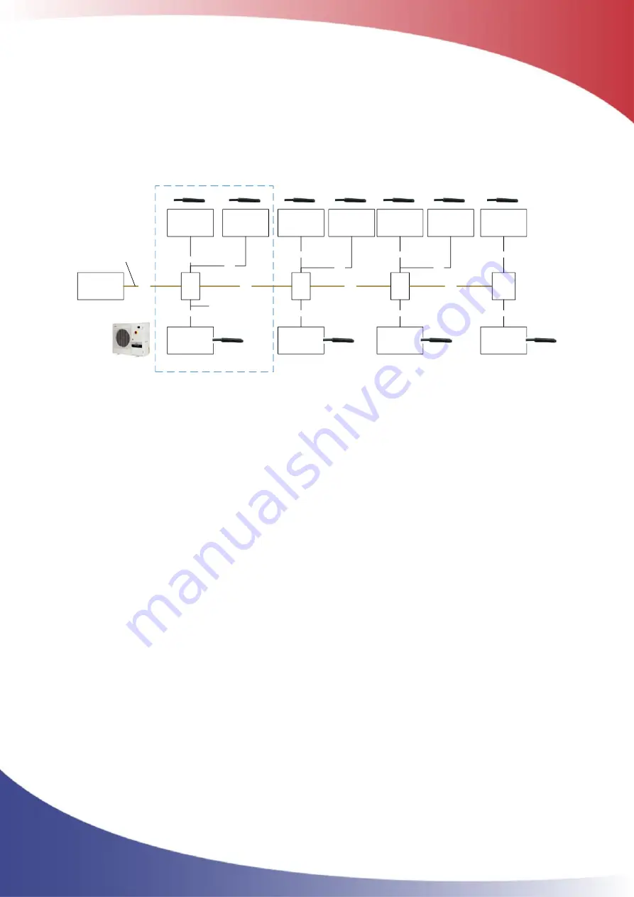
A 1-Wire temperature sensor is a bus sensor and unlike Pt1000 sensors the measured value of the
sensor is not affected by the resistance in the cable between the master (Gateway NX400) and the
slave (sensor). Limitations in number of sensors and cable length as well as the preferred topology
is described below.
ClimaCheck
1-wire master
concom
PA Pro III
Split
(+0.5 m)
Split
(+0.5 m)
< X m
1-wire sensor
(+0.5 m)
1-wire sensor
(+0.5 m)
1-wire sensor
(+0.5 m)
< 3 m
<3 m
< 3 m
< X m
1-wire sensor
(+0.5 m)
1-wire sensor
(+0.5 m)
< 3 m
< 3 m
Split
(+0.5 m)
1-wire sensor
(+0.5 m)
1-wire sensor
(+0.5 m)
1-wire sensor
(+0.5 m)
< 3 m
<3 m
< 3 m
< X m
Split
(+0.5 m)
1-wire sensor
(+0.5 m)
1-wire sensor
(+0.5 m)
1-wire sensor
(+0.5 m)
< 3 m
<3 m
< 3 m
< X m
1-wire bus
Stub
i.e. cold room,
Heating system,
chilled water
i.e. missing unit
temperatures
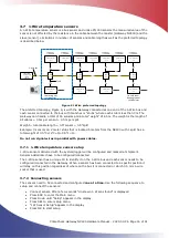
Figure 9 1-Wire preferred topology
The preferred topology, Figure 9, is with the Gateway connected at one end of the 1-Wire bus and
each sensor connected to the bus with
branches or “stubs”
where each stub is less than 3m. The
Gateway can handle a total of 16 sensors and a total
“weight”
of 65 m. The weight is the length of
all 0.5m per 0.5m per split.
Weight = total cable 0.5* 0.5*split
Example: 3 sensors on 2 meter stubs that is located 5 meters from the NX400 with 1 split has a
total weight of 0.5*3+(2*3+5)+0.5*1=14.
Do not run signal wires in parallel with power cables.
3.7.1
1-Wire temperature sensor setup
1-Wire sensors delivered with the system/logger will be configured and marked at shipment.
Sensors added later have to be configured/connected.
The 1-Wire sensor has a unique ID to identify it on the 1-Wire bus and each sensor needs to be
configured/connected in the Gateway. When a sensor has been connected to a specific position it
will stay on this position regardless of where on the bus it is connected or which 3.5 mm 1-wire
socket that is used.
3.7.2
Connecting sensors
The sensors need to be connected and configured
one at a time.
Use the following sequence to
setup and connect the sensors:
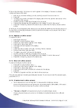
•
Connect sensor.
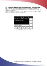
After a few seconds “Unknown 1
-
W sens found” is displayed
•
Press ESC to enter the Main menu
•
Press Down until
“
Setup
”
appears in the display
•
Press SEL to enter setup menu
•
“
1W Sensor Setup
”
appears in the display
•
Press OK to start setup

