ClimaCheck Gateway NX400 Hardware Manual
–
2020-03-26 Page 38 of 41
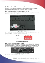
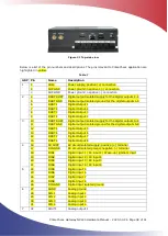
Figure 31 Top-side view
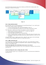
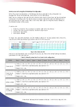
Below is a list of the pin numbers and descriptions. The pins relevant to ClimaCheck application are
highlighted in yellow.
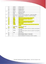
Table 7
GRP Pin
Name
Description
1
1
SUP+
Power supply, positive (+) connection
2
SUP GND
Power ground, negative 1 (-) connection
3
SUP GND
Power ground, negative (-) connection
2
4
DOUT SUPP Digital output isolated supply for the digital outputs 1-4
5
DOUT GND
Digital output isolated ground for the digital outputs 1-4
6
DOUT1
Digital Output 1
7
DOUT2
Digital Output 2
8
DOUT3
Digital Output 3
9
DOUT4
Digital Output 4
3
10
DOUT SUPP Digital output isolated supply for the digital outputs 5-8
11
DOUT GND
Digital output isolated ground for the digital outputs 5-8
12
DOUT5
Digital Output 5
13
DOUT6
Digital Output 6
14
DOUT7
Digital Output 7
15
DOUT8
Digital Output 8
4
16
S0 SUPP
S0 circuit isolated supply, positive (+) terminal
17
DIN GND
S0 circuit isolated ground, negative (-) terminal
18
DIN1
Digital input 1 / S0 input 1 / Wake-up (ignition) input
19
DIN2
Digital input 2 / S0 input 2
20
DIN3
Digital input 3 / S0 input 3
21
DIN4
Digital input 4 / S0 input 4
5
22
DIN5
Digital input 5
23
DIN6
Digital input 6
24
DIN7
Digital input 7
25
DIN8
Digital input 8
26
DIN GND
Digital input isolated ground
6
27
AGND
Analog ground
28
AIN 1
Analog input 1
29
AIN 2
Analog input 2
30
AIN 3
Analog input 3
31
AIN 4
Analog input 4
7
32
AOUT1
Analog output 1

