MatrixMonitor™ IOM - Rev 4 - 4/11/2013
Page 22
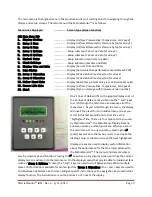
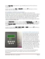
From the “
Control Set Up
” submenu scroll down to highlight “
2. Scale Pressure Signal
”. Press the
(enter) key to display the pressure signal set up screen. The first line will read “
Select Max Pressure
”.
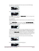
The second line will read “
10V = 10 in WC
”. The number after the = sign is the maximum pressure scale
setting. The last two lines are navigation aids.
Use the + and - keys to raise and lower the pressure scale setting to the required value and press the
(enter) key to confirm the selection and return to the sub menu.
Select the Flow Units
This setting selects the unit of measure that the flow from
both Arrays is reported in. It can be set to “cfm” or “scfm”.
When the setting is “cfm” the control reports flow in
actual cubic feet per minute (ACFM) which is a volumetric
flow rate. When the setting is “scfm”, the control reports
flow in units of standard cubic feet of air per minute
(SCFM) which is an equivalent mass flow rate. It is
determined by calculating the mass flow rate of the air in
lbm/min and dividing it by the standard density of air
(0.075 lbm/ft
3
). When the density of the air entering the
fan is equal to the standard air density, the value reported
for ACFM will be exactly equal to the value reported for
SCFM.
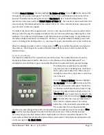
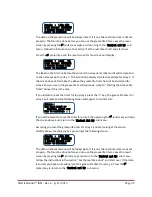
From the “
Control Set Up
” submenu scroll down to highlight “
3. Flow Units
”. Press the
(enter) key
to display the flow unit set up screen. The first line will read “
Select Flow Units
”. The second line will
read “
Units = cfm
”. The text after the = sign is the units used to report flow. The last two lines are
navigation aids.
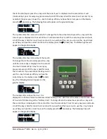
Use the + and - keys to select “
cfm
” or “
scfm
” and press the
(enter) key to confirm the selection and
return to the sub menu.
Enable Modbus Communication with BMS
Digital communication with the Building Management System (BMS) can be enabled or disabled through
the BMS protocol set up screen. When the BMS protocol is set to “None” communication with the BMS
is turned off at the MatrixMonitor™ control unit. When the BMS Protocol is set to “Modbus RTU” the
control unit will actively respond to requests from a “Master” device using the Modbus RTU protocol
over the EIA/TIA 485 multi-port 2 wire communication line. See the subsection labeled “Modbus®
Communications” under “Interface to Building Management System” for a complete discussion about
the digital communication interface provided with MatrixMonitor™.
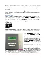
From the “
Control Set Up
” submenu scroll down to highlight “
4. BMS Protocol
”. Press the
(enter)
key to display the flow unit set up screen. The first line will read “
Select BMS Comm:
”. The second line


