MatrixMonitor™ IOM - Rev 4 - 4/11/2013
Page 20
You will get a similar message any display screens that are to display data about Array 2 fans. The
“
Display Airflow
” screen is also different when the number of fans for Array 2 is not 0. (See “Display
Information” below)
In order to set up the data for Array 2 you will have to set the number of fans first before you can do
anything else. If the fan option data has been set for Array 2 and you change the number of fans to 0 the
system will reset all of the Array 2 option data back to the default values. Before it does so you will get
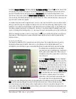
the following message as you exit the “
Number of Fans
” set up screen:
ARRAY 2 WILL DELETE!
PRESS ENTER TO ABORT
ANY OTHER KEY WILL
DELETE ARRAY 2!
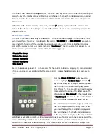
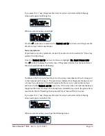
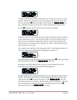
If you press the
(enter) key the Array 2 fan number setting will not be modified and no setting data
will be reset. If you press any other key the number of fans in Array 2 will be set to 0 and all of the Array
2 option data will be reset to the default values. The reverse function of the
(enter) key is to insure
that the set up data is not accidentally erased.
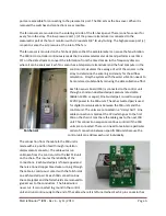
Set the Control Data
Setting up the control information is accomplished
through the “
Control Setup
” submenu. This set of
data entry screens manages the four 0 to 10 VDC
output signals, selects the units that the airflow is
displayed in, sets up the EIA/TIA 485 multipoint
communication line for communication to the building
management system, sets the alarm limits for the
vibration monitor, and initiates the grease life monitor.
See the section “Interface to Building Management
System” for detailed information on the digital
communication capability between MatrixMonitor™
and the site building management system. See the
section “Vibration Monitoring” for an explanation of
the vibration monitoring system. See the section “Lubrication Monitoring” for instructions for the use of
the grease life system.
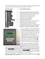
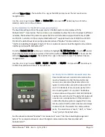
From the main menu, scroll and highlight “
6.Control Setup
”. Press the
(enter) key and the control
setup menu will be displayed.
Menu Lines Displayed
……………….. Screen Type
(Screen Function)
<<<Control Setup>>>
1. Scale Flow Signal
………………… Setup
(scales the 0-10VDC array flow output signals)
2. Scale Pressure Signal
………………… Setup
(scales the 0-10VDC array press rise output signals)
3. Flow Units
………………… Setup
(selects the flow units cfm or scfm)

