MatrixMonitor™ IOM - Rev 4 - 4/11/2013
Page 48
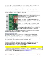
pressure rise. The physical connections to the analog output signals are on the motherboard through
TS8. There are 5 positions on TS8, one for each signal and one for a common ground.
There are three SPDT output relays on MatrixMonitor™. These relays signal operation, alarms, and
warnings. Three connections are available to the contacts on each relay. Each relay is connected to a
separate three position terminal strip. Terminal 1 is for the NO (normally open) contact, terminal 2 is for
common, and terminal 1 is for the NC (normally closed) contact.
Relay 1 is connected to TS5. It switches when MatrixMonitor™
powers up. It is used to signal the BMS that the control is turned
on and available. As long as the control has power and is
operating this relay will be switched on.
Relay 2 is connected to TS6. It switches when MatrixMonitor™
detects a fan failure. The red LED on the key pad display unit will
light when this relay is switched on.
Relay 3 is connected to TS7. It switches when MatrixMonitor™
determines an alarm condition. Alarm conditions would include
a fan in surge, an inoperative fan sensor, excessive vibration,
lubrication alert, or several other conditions. The yellow LEDs on
the key pad display will light when this relay is switched on.
The sample wiring diagram in the appendix of this document shows the physical connections available
between the MatrixMonitor™ and the building management system.
Modbus® Communications
The Modbus® protocol was introduces by Modicon, Inc. for use in control environments featuring
Modicon programmable controllers. Due to its ease of use and implementation, this common PLC
language was adopted as a standard for integration of a wide variety of Master controllers and slave
devices. Because so many industrial and commercial control devices support this protocol most Building
Management Systems have provisions to communicate with Modbus® devices.
Modbus is a serial, asynchronous protocol. Transmissions are half-duplex, with a single master
controlling one or more slaves. MatrixMonitor™ is configured as a slave to communicate with a BS
system acting as the master on the Modbus® network.
The physical connection layer used by
MatrixMonitor® is EIA/TIA 485 commonly referred to as RS485.
CAUTION
The Modbus® specification allows for two different and distinct transmission message modes, ASCII and RTU.
MatrixMonitor only supports RTU.
For more information about the Modbus® protocol visit


