background image

Installation Manual 

97B0055N03

Rev.: 11/3/17

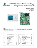
ATC32U03 iGate

 Communicating, 

Programmable Thermostat

Table of Contents

Caution:

These instructions are intended to be used by the installer or service personnel.  End users are NOT advised to change or 
modify any of these settings.  Doing so may cause the equipment to stop working properly and/or may void the warranty on 
both the thermostat and the equipment.

Section Title 

Page


Safety/Installation Considerations  

  3

1.0  

User Menu Settings  

  4

2.0  

Installer Menu Settings  

  6


2.1  

Installer Menu Settings Access  

  6


2.2  

Thermostat Confi guration  

6

3.0  

System Confi guration  

7

 3.1 

  Airfl ow Selection  

7


3.2  

Option Selection  

7


3.3  

Unit Confi guration  

8


3.4  

Pump Confi guration  

8


3.5  

Valve Confi guration 

9


3.6  

Multi-Unit Confi guration  

9

4.0  

Accessory Confi guration  

10


4.1  

Air Filter  

10

 4.2 

  Humidifi er  

10


4.3  

UV Lamp  

10

Section Title 

Page


4.4  

Air Cleaner 

10

5.0  

Input Dealer Information  

10

6.0  

Humidity Confi guration  

11

7.0  

Temperature Algorithm  

11

8.0  

Demand Reduction Confi guration  

12

9.0  

Service Mode  

12


9.1  

Manual Operation  

12


9.2  

Control Diagnostics  

12


9.3  

Dipswitch Confi guration  

13


9.4  

Fault History  

13


9.5  

Clear Fault History  

14


9.6  

Multi-Unit Diagnostics  

14


9.7  

Multi-Unit Fault Information  

15

10.0  

Restore Defaults  

15

11.0  

Revision History  

16

Summary of Contents for iGate ATC32U03

Page 1: ...Access 6 2 2 Thermostat Configuration 6 3 0 System Configuration 7 3 1 Airflow Selection 7 3 2 Option Selection 7 3 3 Unit Configuration 8 3 4 Pump Configuration 8 3 5 Valve Configuration 9 3 6 Multi...

Page 2: ...This page was intentionally left blank...

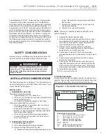
Page 3: ...need not be leveled for proper operation and mark wall through 2 mounting holes 5 Drill two 3 16 in mounting holes in wall where marked Note Mounting holes on thermostat are designed to fit on a hori...

Page 4: ...ontrol algorithm must be configured for Differential control to access the Differential settings by installer 1 1 2 HUMIDITY OFFSET If you find that the Humidity level displayed on the thermostat does...

Page 5: ...erature at the time when Demo Mode is entered The unit will operate in heating or cooling based upon the following algorithm 1 3 3 EXITING DEMO MODE To exit demo mode remove power to the thermostat St...

Page 6: ...onds while the thermostat is in OFF Mode 2 2 THERMOSTAT CONFIGURATION Upon initial power up the communicating thermostat will prompt the installer for the thermostat configuration settings Model numbe...

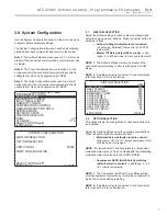
Page 7: ...e center button to select each item Airflow Settings defaults stored in control valid range obtained from control in 25 CFM increments Blower Off Delay default 60 seconds valid range 0 to 255 seconds...

Page 8: ...OP CONFIG VS PUMP SELECT OPTION PREVIOUS SAVE 3 4 PUMP CONFIGURATION vFlow vs internal flow control pump can be controlled either through temperature differential Delta T or can be set to specific spe...

Page 9: ...figuration instructions MODULATING VALVE CONFIGURATION OFF POSITION 0 0 VALVE CONTROL DELTA T HEATING DELTA T 7 F COOLING DELTA T 10 F MAXIMUM HEAT LWT 80 F MINIMUM COOL LWT 40 F PREVIOUS SELECT For c...

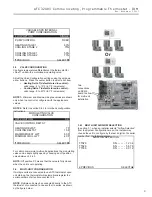
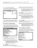
Page 10: ...ts Calendar Time default Off valid range Off 3 to 24 months in 3 month increments 4 3 UV LAMP This feature displays an alert to remind the user to change the UV lamps after the selected time has passe...

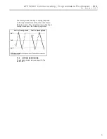
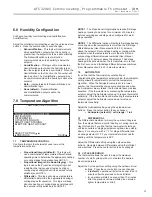
Page 11: ...ershooting the temperature setpoint adjust the Anticipator value up to reduce thermostat sensitivity If the thermostat is undershooting the temperature setpoint adjust the Anticipator value down to in...

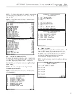
Page 12: ...the center button to save changes Smart Heat Staging default Off options OFF 5 120 minutes in 5 minute increments 7 6 ELECTRIC HEAT LOCKOUT Electric heat lockout keeps electric heat turned off if the...

Page 13: ...3 1 ON FACTORY SETTING 2 OFF HWG TEST OFF 3 OFF HWG SP 125 4 OFF HWG DISABLED JW3 LT1 SETTING WELL PREVIOUS 9 3 DIPSWITCH CONFIGURATION Dipswitch Configuration mode allows the service personnel to vie...

Page 14: ...9 7 9 4 4 Configuration Conditions Displays the status of all dipswitch settings that were recorded at the time the fault occurred NOTE If multiple units are connected to one thermostat refer to secti...

Page 15: ...onnected directly to the ATC thermostat or connected to one another in series as shown by the figure below CONTROL DIAGNOSTICS TT026 S N 1 2 3 4 TT026 S N 5 6 7 8 TT038 S N 9 0 1 2 PREVIOUS SELECT TT0...

Page 16: ...imateMaster s opinion or commendation of its products ClimateMaster Inc 2012 97B0055N03 7300 S W 44th Street Oklahoma City OK 73179 Phone 405 745 6000 Fax 405 745 6058 climatemaster com Rev November 3...

Reviews: