44
C l i m a t e M a s t e r W a t e r- S o u r c e H e a t P u m p s
C L I M A T E M A S T E R W A T E R - S O U R C E H E A T P U M P S
Tr a n q u i l i t y
®
2 0 ( T S ) S e r i e s
R e v. : 0 6 / 1 7 / 1 5
ClimaDry
®
Sequence Of Operation
A heat pump equipped with ClimaDry
®
can operate
in three modes, cooling, cooling with reheat, and
heating. The cooling/heating modes are like any other
ClimateMaster WSHP. The reversing valve (“O” signal)
is energized in cooling, along with the compressor
contactor(s) and blower relay. In the heating mode the
reversing valve is de-energized. Almost any thermostat
will activate the heat pump in heating or cooling modes.
The DXM microprocessor board, which is standard with
the ClimaDry
®
option, will accept either heat pump (Y,O)
thermostats or non-heat pump (Y,W) thermostats.
The reheat mode requires either a separate humidistat/
dehumidistat or a thermostat that has an integrated
dehumidifi cation function for activation. The DXM
board is confi gured to work with either a humidistat or
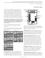
dehumidistat input to terminal “H” (DIP switch settings
for the DXM board are shown in table 6). Upon receiving
an “H” input, the DXM board will activate the cooling
mode and engage reheat. Table 7 shows the relationship
between thermostat input signals and unit operation.
There are four operational inputs for single stage units
and six operational inputs for dual stage units:
-Fan Only
-1st Stage Cooling
-2nd Stage Cooling
-1st Stage Heating
-2nd Stage Heating
-Reheat Mode
• Fan Only:
A (G) call from the thermostat to the (G
terminal of the DXM control board will bring the unit
on in fan only mode.
• 1st Stage Cooling:
A simultaneous call from (G),
(Y1), and (O) to the (G), (Y1), (O/W2) terminals of the
DXM control board will bring the unit on in 1st Stage
Cooling.
• 2nd Stage Cooling:
A simultaneous call from (G),
(Y1), (Y2), and (O) to the (G), (Y1), (Y2), and (O/W2)
terminals of the DXM control board will bring the unit
on in 2nd Stage Cooling. When the call is satisfied
at the thermostat the unit will continue to run in 1st
Stage Cooling until the 1st Stage Cooling call is
removed or satisfied, shutting down the unit.
Note:
Not all units have two-stage cooling functionality
(e.g. GC series units).
• 1st Stage Heating:
A simultaneous call from (G) and
(Y1) to the (G) and (Y1) terminals of the DXM control
board will bring the unit on in 1st Stage Heating.
• 2nd Stage Heating:
A simultaneous call from (G),
(Y1), and (Y2) to the (G), (Y1), and (Y2) terminals of the
DXM control board will bring the unit on in 2nd Stage
Heating. When the call is satisfied at the thermostat
the unit will continue to run in 1st Stage Heating
until the call is removed or satisfied, shutting down
the unit. NOTE: Not all units have two-stage heating
functionality.
• Reheat Mode
: A call from the Humidistat/
Dehumidistat to the (H) terminal of the DXM control
board will bring the unit on in Reheat Mode if there
is no call for cooling at the thermostat. When the
Humidistat Dehumidification call is removed or
satisfied the unit will shut down. Note: Cooling always
overrides Reheat Mode. In the Cooling mode, the unit
cools and dehumidifies. If the cooling thermostat is
satisfied but there is still a call for dehumidification,
the unit will continue to operate in Reheat Mode.
ClimaDry
®
Component Functions
The ClimaDry
®
option consists of the following
components:
• Proportional Controller
• Supply Air Sensor
• Motorized Valve
• Loop Pump
• Hydronic Coil
The Proportional Controller operates on 24 VAC power
supply and automatically adjusts the water valve based
upon the Supply Air Sensor. The Supply Air Sensor
senses supply air temperature at the blower inlet
providing the input signal necessary for the proportional
control to drive the motorized valve during the reheat
mode of operation. The Motorized Valve is a proportional
actuator/three-way valve combination used to divert
the condenser water from the coax to the hydronic
reheat coil during the reheat mode of operation. The
proportional controller sends a signal to the motorized
valve based on the supply air temperature of the supply
air sensor.
The Loop Pump circulates condenser water through
the hydronic reheat coil during the reheat mode of
operation. In this application, the loop pump is only
energized during the reheat mode of operation. The
Hydronic Coil is utilized during the reheat mode of
operation to reheat the air to the setpoint of the
proportional controller. Condenser water is diverted by
the motorized valve and pumped through the hydronic
coil by the loop pump in proportion to the control
setpoint. The amount of reheating is dependent on
the setpoint and how far from setpoint the supply air
temperature is. The factory setpoint is 72°F [22.2°C],
generally considered “neutral” air.
ClimaDry
®
Modulating Reheat Option


