background image

7

c l i m a t e m a s t e r. c o m

T H E   S M A R T   S O L U T I O N   F O R   E N E R G Y   E F F I C I E N C Y

Tr a n q u i l i t y

®

  2 0   ( T S )   S e r i e s

R e v. :   0 6 / 1 7 / 1 5

Horizontal Installation

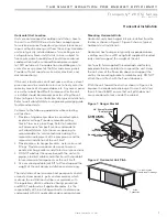
Mounting Horizontal Units

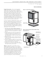
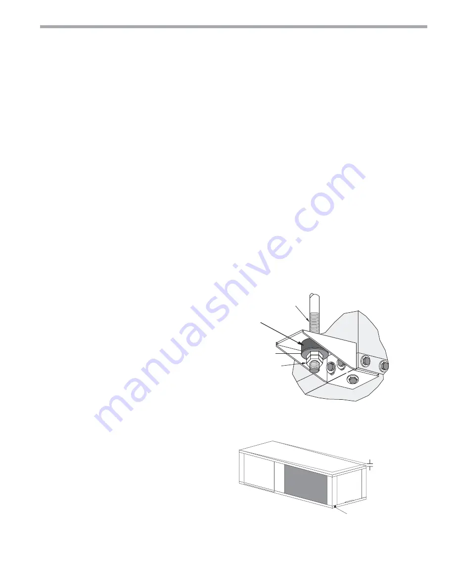
Horizontal units have hanger kits pre-installed from the 
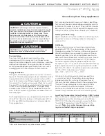
factory as shown in Figure 1. Figure 3 shows a typical 
horizontal unit installation.

Horizontal heat pumps are typically suspended above 
a ceiling or within a soffi t using fi eld supplied, threaded 
rods sized to support the weight of the unit.

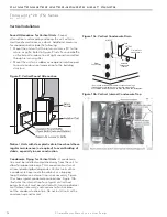
Use four (4) fi eld supplied threaded rods and factory 
provided vibration isolators to suspend the unit. Hang 
the unit clear of the fl oor slab above and support the 
unit by the mounting bracket assemblies only. DO NOT 
attach the unit fl ush with the fl oor slab above.

Pitch the unit toward the drain as shown in Figure 2 to 
improve the condensate drainage. On small units (less 
than 2.5 tons/8.8kW) ensure that unit pitch does not 
cause condensate leaks inside the cabinet.

Figure 1: Hanger Bracket

Figure 2: Horizontal Unit Pitch

>PP@7KUHDGHG

5RGE\RWKHUV

9LEUDWLRQ,VRODWRU

IDFWRU\VXSSOLHG

:DVKHU

E\RWKHUV

'RXEOH+H[1XWV

E\RWKHUV

1/4” (6.4mm) pitch
toward drain for drainage

Drain 

Connection

Horizontal Unit Location

Units are not designed for outdoor installation. Locate 
the unit in an INDOOR area that allows enough space 
for service personnel to perform typical maintenance or 
repairs without removing unit from the ceiling. Horizontal 
units are typically installed above a false ceiling or in a 
ceiling plenum. Never install units in areas subject to 
freezing or where humidity levels could cause cabinet 
condensation (such as unconditioned spaces subject 
to 100% outside air). Consideration should be given to 
access for easy removal of the fi lter and access panels. 
Provide suffi cient room to make water, electrical, and 
duct connection(s). 

If the unit is located in a confi ned space, such as a closet, 
provisions must be made for return air to freely enter the 
space by means of a louvered door, etc. Any access panel 
screws that would be diffi cult to remove after the unit 
is installed should be removed prior to setting the unit. 
Refer to Figure 3 for an illustration of a typical installation. 
Refer to unit submittal data or engineering design guide 
for dimensional data.

Conform to the following guidelines when selecting 
unit location:
1.  Provide a hinged access door in concealed-spline 

or plaster ceilings. Provide removable ceiling 
tiles in T-bar or lay-in ceilings. Refer to horizontal 
unit dimensions for specifi c series and model in 
unit submittal data. Size the access opening to 
accommodate the service technician during the 
removal or replacement of the compressor and the 
removal or installation of the unit itself.

2.  Provide access to hanger brackets, water valves and 

fi ttings. Provide screwdriver clearance to access 
panels, discharge collars and all electrical connections.

3.  DO NOT obstruct the space beneath the unit with 

piping, electrical cables and other items that prohibit 
future removal of components or the unit itself.

4.  Use a manual portable jack/lift to lift and support the 

weight of the unit during installation and servicing.

The installation of water source heat pump units and all 
associated components, parts and accessories which 
make up the installation shall be in accordance with 
the regulations of ALL authorities having jurisdiction 
and MUST conform to all applicable codes. It is the 
responsibility of the installing contractor to determine 
and comply with ALL applicable codes and regulations.

Summary of Contents for Tranquility 20 TSD 006 Series

Page 1: ...rmance Data ECM Motor Standard Unit No Reheat 30 TS Blower Performance Data Standard Unit No Reheat PSC Motor 31 TS Blower Performance Data Units with ClimaDry PSC Motor 32 ECM Blower Control 33 Typic...

Page 2: ...2 ClimateMaster Water Source Heat Pumps CL I MATEM ASTER WATER SOURCE HEAT PUMPS Tran q u i l i t y 20 TS Series Rev 06 17 15 This Page Intentionally Left Blank...

Page 3: ...06 012 E 265 60 1 N 575 60 3 F 460 60 3 AVAILABLE VOLTAGES 006 E G 009 E G 012 E G 018 E G 024 E F G H 030 E F G H 036 E F G H 042 E F G H N 048 E F G H N 060 E F G H N 070 F G H N OPTION 1 A J K 2 C...

Page 4: ...Application and Service Manual should be read and understood before attempting to service refrigerant circuits with HFC 410A Inspection Upon receipt of the equipment carefully check the shipment agai...

Page 5: ...g heat pumps General Information Pre Installation Installation Operation and Maintenance instructions are provided with each unit Horizontal equipment is designed for installation above false ceiling...

Page 6: ...x 20 406 x 508 24 x 24 610 x 610 28 x 24 711 x 610 28 x 24 711 x 610 28 x 30 711 x 762 2 16 x 30 2 406 x 762 2 16 x 30 2 406 x 762 1 16 x 30 1 20 x 30 1 406 x 762 1 508 x 762 1 16 x 30 1 20 x 30 1 40...

Page 7: ...should be given to access for easy removal of the filter and access panels Provide sufficient room to make water electrical and duct connection s If the unit is located in a confined space such as a...

Page 8: ...LW 3RZHU LVFRQQHFW 3RZHU LULQJ QVXODWHG VXSSO GXFW ZLWK DW OHDVW RQH GHJ HOERZ WR UHGXFH DLU QRLVH 5HWXUQ LU 6XSSO LU 8QLW DQJHU PP WKUHDGHG URGV 8QLW 3RZHU OH LEOH XFW RQQHFWRU 2SWLRQDO RZ 3UHVVXUH U...

Page 9: ...ft out the access panel and set aside Lift and rotate the discharge panel to the other position as shown being careful with the blower wiring 3 Check blower wire routing and connections for tension or...

Page 10: ...ED IN THE DRAIN LINE IT MUST BE LOCATED AFTER THE TRAP IN THE DIRECTION OF THE CONDENSATE FLOW Duct System Installation Proper duct sizing and design is critical to the performance of the unit The duc...

Page 11: ...vered door etc Any access panel screws that would be difficult to remove after the unit is installed should be removed prior to setting the unit Refer to Figures 7 and 8 for typical installation illus...

Page 12: ...low for proper drainage This connection must meet all local plumbing building codes Vertical units utilize a condensate hose inside the cabinet as a trapping loop therefore an external trap is not nec...

Page 13: ...mperature drops below the dew point insulation is required for ground loop applications in most climates Pipe joint compound is not necessary when Teflon thread tape is pre applied to hose assemblies...

Page 14: ...lve and or J type swivel connection Balancing valves and an external low pressure drop solenoid valve for use in variable speed pumping systems may also be included in the hose kit The piping system s...

Page 15: ...your local sales office should be consulted to determine the antifreeze best suited to your area Freeze protection should be maintained to 15 F 9 C below the lowest expected entering loop temperature...

Page 16: ...umps CL I MATEM ASTER WATER SOURCE HEAT PUMPS Tran q u i l i t y 20 TS Series Rev 06 17 15 Ground Loop Heat Pump Applications Figure 13 Typical Ground Loop Application High and Low Voltage Knockouts V...

Page 17: ...iping may cause failure of the PVC CPVC PVC CPVC piping should never be used as supply or return water piping with water source heat pump products containing HFC 410A as system failures and property d...

Page 18: ...sired flow of 1 5 to 2 gpm per ton 2 0 to 2 6 l m per kW is achieved A second method of flow control requires a flow control device mounted on the outlet of the water control valve The device is typic...

Page 19: ...oride Levels 10 C 24 C 38 C Copper Cupronickel 20ppm NR NR 150 ppm NR NR 304 SS 400 ppm 250 ppm 150 ppm 316 SS 1000 ppm 550 ppm 375 ppm Titanium 1000 ppm 550 ppm 375 ppm Erosion and Clogging Particula...

Page 20: ...1 0 1 7 7 9 9 5 15 1 3 9 0 10 6 15 N 575 60 3 518 633 1 4 8 33 0 1 4 6 2 7 4 15 N A N A N A N A 060 G 208 230 60 1 197 254 1 26 4 134 0 3 8 30 2 36 8 60 1 1 31 3 37 9 60 H 208 230 60 3 197 254 1 16 11...

Page 21: ...0 6 1 7 4 15 0 7 6 8 8 1 15 036 G 208 230 60 1 197 254 1 16 0 77 0 2 2 18 2 22 2 35 0 8 19 0 23 0 35 E 265 60 1 239 292 1 12 2 72 0 1 7 13 9 17 0 25 0 7 14 6 17 7 25 H 208 230 60 3 197 254 1 10 71 0...

Page 22: ...1 10 71 0 3 9 13 9 16 4 25 0 8 14 7 17 2 25 F 460 60 3 414 506 1 4 7 38 0 3 2 7 9 9 1 15 0 7 8 6 9 8 15 042 G 208 230 60 1 197 254 1 16 7 79 3 9 20 6 24 8 40 0 8 21 4 25 6 40 E 265 60 1 239 292 1 13...

Page 23: ...7 4 15 0 7 6 8 8 1 15 036 G 208 230 60 1 197 254 1 16 0 77 0 1 8 17 8 21 8 35 0 8 18 6 22 6 35 E 265 60 1 239 292 1 12 2 72 0 2 0 14 2 17 3 25 0 7 14 9 18 0 30 H 208 230 60 3 197 254 1 10 71 0 1 8 11...

Page 24: ...1 12 2 72 0 1 7 13 9 29 2 25 0 7 14 6 17 7 25 H 208 230 60 3 197 254 1 10 71 0 2 2 12 2 14 7 25 0 8 13 0 15 5 25 F 460 60 3 414 506 1 4 7 38 0 1 0 5 7 6 9 15 0 7 6 4 7 6 15 042 G 208 230 60 1 197 254...

Page 25: ...12 2 72 0 3 2 15 4 30 7 30 0 7 16 1 19 2 30 H 208 230 60 3 197 254 1 10 71 0 3 9 13 9 16 4 25 0 8 14 7 17 2 25 F 460 60 3 414 506 1 4 7 38 0 3 2 7 9 9 1 15 0 7 8 6 9 8 15 042 G 208 230 60 1 197 254 1...

Page 26: ...gure 16 Most ClimateMaster units are shipped on the medium speed tap Consult submittal data or engineering design guide for specific unit airflow tables Typical unit design delivers rated airflow at n...

Page 27: ...Selection The CXM DXM control allows the field selection of low water or water antifreeze solution temperature limit by clipping jumper JW3 which changes the sensing temperature associated with therm...

Page 28: ...include 75VA transformer Figure 20 AVM Valve Wiring Figure 21 Taco SBV Valve Wiring C C Thermostat Y1 1 2 3 Y1 AVM Taco Valve Heater Switch Water Solenoid Valves An external solenoid valve s should b...

Page 29: ...te mounting holes and drill holes with a 3 16 5mm bit Install supplied anchors and secure plate to the wall Thermostat wire must be 18 AWG wire Representative thermostat wiring is shown in Figures 22a...

Page 30: ...500 900 1100 500 3 1100 2 740 900 450 580 700 450 800 950 450 2 950 1 660 800 400 640 780 400 1 780 036 0 90 1 2 4 1150 1400 700 900 1090 700 1150 1400 700 4 1400 3 1020 1250 630 800 980 630 1020 1250...

Page 31: ...LO 1321 1294 1263 1226 1182 1130 1064 980 871 729 042 HI 1400 960 1808 1759 1723 1680 1617 1524 1399 1247 1075 MED 1537 1518 1494 1459 1408 1338 1247 1134 1001 LO 1323 1309 1284 1246 1192 1122 1036 9...

Page 32: ...loss Example Reheat coil loss can be determined from the above table Coil velocity FPM Airflow CFM Face Area sq ft 1 TSH036 has a face area of 4 86 sq ft see physical data table 2 At 1 100 cfm coil ve...

Page 33: ...e speed tap setting to airflow in CFM Heating Settings The heating setting determines the heating CFM Tap 1 is the lowest CFM setting while tap 4 is the highest CFM setting Consult submittal data or s...

Page 34: ...ations catalog for the specific unit series and model to correlate speed tap to airflow in CFM The dehumidification mode can be enabled in two ways 1 Constant Dehumidification Mode When the dehumidifi...

Page 35: ...35 climatemaster com THE SMART SOLUTION FOR ENERGY EFFIC I E NC Y Tranquility 20 TS Ser ies R ev 0 6 1 7 1 5 Typical Wiring Diagram Units with CXM Board and ECM Fan Motor Single Phase...

Page 36: ...6 ClimateMaster Water Source Heat Pumps CL I MATEM ASTER WATER SOURCE HEAT PUMPS Tran q u i l i t y 20 TS Series Rev 06 17 15 Typical Wiring Diagram Units with CXM Board and PSC Fan Motor Single Phase...

Page 37: ...37 climatemaster com THE SMART SOLUTION FOR ENERGY EFFIC I E NC Y Tranquility 20 TS Ser ies R ev 0 6 1 7 1 5 Typical Wiring Diagram Units with DXM Board and PSC Fan Motor Three Phase...

Page 38: ...eMaster Water Source Heat Pumps CL I MATEM ASTER WATER SOURCE HEAT PUMPS Tran q u i l i t y 20 TS Series Rev 06 17 15 Typical Wiring Diagram Units with CXM Board ECM Fan Motor and MPC DDC CONTROLS SIN...

Page 39: ...o 24VAC or to be a dry contact no connection Not Clipped AL2 connected to R Clipped AL2 dry contact no connection DIP Switches Note In the following field configuration options DIP switches should onl...

Page 40: ...Jumper 3 JW3 LT1 Low Temp provides field selection of temperature limit setting for LT1 of 30 F or 10 F 1 F or 12 C refrigerant temperature DXM Controls Table 5b DXM LED And Alarm Relay Operations Not...

Page 41: ...on DIP 1 4 On Heat Pump Off Heat Cool 1 4 Thermostat type O B DIP 1 4 provides selection of thermostat type for reversing valve activation Heat pump thermostats with O output reversing valve energized...

Page 42: ...remain open for 30 continuous seconds during on cycle to be recognized as a low pressure fault If the low pressure switch is open for 30 seconds prior to compressor power up it will be considered a l...

Page 43: ...LED Diagnostic Features The LED on the CXM board advises the technician of the current status of the CXM control The LED can display either the current CXM mode or the last fault in memory if in test...

Page 44: ...n in 1st Stage Heating 2nd Stage Heating A simultaneous call from G Y1 and Y2 to the G Y1 and Y2 terminals of the DXM control board will bring the unit on in 2nd Stage Heating When the call is satisfi...

Page 45: ...ejection to the building loop Although the ClimaDry option will work fine with low EWTs overcooling of the space may result with well water systems or on rare occasions with ground loop geothermal sys...

Page 46: ...um levels the other two factors should be at normal levels to ensure proper unit operation Extreme variations in temperature and humidity and or corrosive water or air will adversely affect unit perfo...

Page 47: ...system and add trisodium phosphate in a proportion of approximately one pound per 150 gallons 8 kg per 1000 l of water or other equivalent approved cleaning agent Reset the boiler to raise the loop t...

Page 48: ...nal of the DXM controller as shown in figure 1 to energize the modulating three way dehumidifica tion valve Once energized the valve will take 45 75 seconds to fully shift Continue flushing during thi...

Page 49: ...and fittings see table 3 System flushing Verify that all hoses are connected end to end when flushing to ensure that debris bypasses the unit heat exchanger water valves and other components Water use...

Page 50: ...mparing the pressure drop across the heat exchanger to table 9 In S I units the formula is as follows HR kW TD x l s x 4 18 f Check air temperature drop across the air coil when compressor is operatin...

Page 51: ...al panel Exercise caution when working with energized equipment CAUTION Verify that ALL water control valves are open and allow water flow prior to engaging the compressor Freezing of the coax or wate...

Page 52: ...7 1 8 12 3 12 0 0 757 45 3 9 26 9 3 2 22 0 3 2 21 9 3 0 21 0 060 7 5 0 473 28 1 3 9 1 0 6 4 3 0 5 3 2 0 5 3 4 11 3 0 713 43 3 5 24 5 2 5 16 9 2 1 14 2 2 0 13 6 15 0 0 947 57 6 1 42 0 4 7 32 4 4 1 28...

Page 53: ...132 142 132 142 132 142 215 235 200 220 185 205 10 15 10 15 10 15 8 13 7 12 6 11 18 8 20 8 14 1 16 1 9 4 11 4 20 26 20 26 20 26 104 114 106 116 108 118 309 329 312 332 315 335 8 12 8 12 8 12 7 12 7 1...

Page 54: ...201 24 29 24 29 24 29 10 15 8 13 8 13 15 7 17 7 11 6 13 6 7 6 9 6 18 24 18 24 18 24 102 112 106 116 110 120 313 333 314 334 316 336 8 12 8 12 8 12 8 13 8 13 8 13 8 9 10 9 6 7 8 7 4 5 6 5 22 28 23 29...

Page 55: ...4 18 24 50 1 5 2 25 3 136 146 136 146 136 146 211 231 197 217 183 203 11 16 11 16 11 16 6 11 5 10 5 10 20 6 22 6 14 8 16 8 9 11 17 23 17 23 17 23 99 109 103 113 108 118 302 322 306 326 311 331 10 15 1...

Page 56: ...ethanol antifreeze solution 070 Full Load Cooling without HWG active Full Load Heating without HWG active Entering Water Temp F Water Flow GPM ton Suction Pressure PSIG Discharge Pressure PSIG Superhe...

Page 57: ...s must be clean to obtain maximum performance Filters should be inspected every month under normal operating conditions and be replaced when necessary Units should never be operated without a filter W...

Page 58: ...Check slope of unit toward outlet Poor venting Check vent location X Moisture on sensor Check for moisture shorting to air coil X X Plugged air filter Replace air filter x X Restricted Return Air Flo...

Page 59: ...low restrictions Too high of external static Check static vs blower table X Reduced or no water flow in cooling Check pump operation or valve operation setting Check water flow Adjust to proper flow r...

Page 60: ..._____________________ Sales Order No __________________________________________ In order to minimize troubleshooting and costly system failures complete the following checks and data entries before th...

Page 61: ...1 1 6 6 36 6 7 36 6 7 5 2 3 7 1 48 1 3 16 21 9 9 5 2 36 6 7 36 6 7 7 5 1 7 5 287 36 36 7 5 1 7 5 287 36 36 8VH IRU ZDWHU IRU DQWLIUHH H 7 5 5 5 6 6 1 3 6 1625 3 16 21 9 9 7 5 5 5 3 6 6 1 27 5 6 2 75 5...

Page 62: ...t of insuf cient or incorrect system design or the improper application of CM s products CM is not responsible for 1 The costs of any uids refrigerant or other system components or associated labor to...

Page 63: ...ge or insuffi cient performance as a result of insuffi cient or incorrect system design or the improper application installation or use of CM s products or 14 Electricity or fuel costs or any increase...

Page 64: ...ed 97B0075N06 97B0075N06 7300 S W 44th Street Oklahoma City OK 73179 Phone 405 745 6000 Fax 405 745 6058 climatemaster com ISO 9001 2008 Certified Quality First Always R M A N U F A C T U R E R CERTIF...

Reviews: