background image

33

c l i m a t e m a s t e r. c o m

Tranquility

®

 30 Digital (TE) Series IOM - 60Hz HFC-410A

R e v. :   2 9   M a y,   2 0 1 5 J

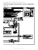
DXM2 Wiring Diagram with Motorized Modulating Water Valve - 

96B0005N62 - Part 1 of 2

This diagram includes typical wiring details but is not applicable to all units. For speci

fi

 c unit wiring, refer to the diagram or the 

units’ control panel.

Summary of Contents for Tranquility 30 TE026

Page 1: ...mperature Cutout Selection 20 Closed Loop External Central 21 Pumping Applications Open Loop or Ground Water 22 23 Heat Pump Applications Water Quality Requirements 24 Hot Water Generator 25 27 Electrical Line Voltage 28 Electrical Low Voltage Wiring 29 Electrical Thermostat Wiring 30 Wiring Diagrams 31 34 ECM Blower Control 35 Blower Data 36 DXM2 Controls 37 DXM2 Layout and Connection 38 Unit Com...

Page 2: ...This page was intentionally left blank ...

Page 3: ...product or property damage NOTICE Notification of installation operation or maintenance information which is important but which is not hazard related WARNING WARNING The EarthPure Application and Service Manual should be read and understood before attempting to service refrigerant circuits with HFC 410A NOTE Above model nomenclature is a general reference Consult individual specification sections...

Page 4: ...ering and shipping information to verify that the correct unit has been shipped 2 Keep the cabinet covered with the original packaging until installation is complete and all plastering painting etc is finished 3 Verify refrigerant tubing is free of kinks or dents and that it does not touch other unit components 4 Inspect all electrical connections Connections must be clean and tight at the termina...

Page 5: ...anel ASP Additional Service Panel not required ASP Isometric View BSP CCP 2 61cm Optional Service Access Left Rtn right Opposite 2 61cm Service ASP Vertical Unit Location Packaged units are not designed for outdoor installation Locate the unit in an INDOOR area that allows enough space for service personnel to perform typical maintenance or repairs without removing the unit from the installed loca...

Page 6: ...e removal of components or the unit itself 4 Use a manual portable jack lift to lift and support the weight of the unit during installation and servicing Mounting Horizontal Units Horizontal units have hanger kits pre installed from the factory as shown in Figure 4 Figure 6 shows a typical horizontal unit installation Horizontal heat pumps are typically suspended above a ceiling or within a soffit...

Page 7: ... thorough water rinse should follow Figure 6b Typical Ground Water Horizontal Unit Installation with Internal Motorized Modulating Valve Pressure Tank Ball Valves Internal Motorized Modulating Valve Water Pressure Ports Boiler Drains DWHU 2XW DWHU Q by others Unit Power Disconnect by others Power Wiring Supply Air 3 8 10mm threaded rods Unit Power Flexible Duct Connector Unit Hanger Platform Retur...

Page 8: ...ove the screws as shown in Figure 7 to free top panel and discharge panel 2 Lift out the access panel and set aside Lift and rotate the discharge panel to the other position as shown being careful with the blower wiring 3 Check blower wire routing and connections for tension or contact with sheet metal edges Reroute if necessary 4 Check refrigerant tubing for contact with other components 5 Reinst...

Page 9: ...T IS INSTALLED IN THE DRAIN LINE IT MUST BE LOCATED AFTER THE TRAP IN THE DIRECTION OF THE CONDENSATE FLOW Gasket Swivel Nut Stainless steel snap ring Brass Adaptor Hand Tighten Only Do Not Overtighten Figure 10 Water Connections Water Connections Residential models utilize swivel piping fittings for water connections that are rated for 450 psi 3101 kPa operating pressure The connections have a ru...

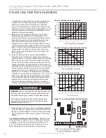
Page 10: ...ternal Flow Controller For Closed Loop Applications This is the most common configuration for closed loops With this factory installed standard option the unit is built with an Internal Variable Speed Pump and other components to flush and operate the unit correctly including an expansion tank flush ports and flushing valves The pump speed is controlled by the DXM2 control based on the difference ...

Page 11: ...ormally low for cooling or abnormally high for heating the DXM2 controller will maintain a constant leaving water temperature which will allow the unit to operate properly under those conditions The internal expansion tank helps to maintain constant loop pressure despite the natural expansion and contraction of the loop as the seasons and loop temperatures vary The expansion tank also helps to avo...

Page 12: ... 2 13 00 14 8 14 00 13 4 15 00 12 1 16 00 10 8 17 00 9 5 18 00 8 2 19 00 7 0 20 00 5 8 Figure 13 Magna Geo 25 140 High Head Variable Pump Performance Figure 13a UPM Geo 25 85 Standard Head Variable Pump Performance 0 10 20 30 40 50 60 0 5 10 15 20 25 30 35 40 Head Ft Flow GPM Magna Geo 25 140 Pump Curve GPM Head ft 0 0 44 7 1 0 45 4 2 0 46 1 3 0 46 8 4 0 47 5 5 0 47 7 6 0 47 1 7 0 46 1 8 0 45 3 9 ...

Page 13: ...m s in all piping using a filter in the loop return line of the flush cart to eliminate debris from the loop system See Table 1 for flow rate required to attain 2fps 0 6 m s The steps below must be followed for proper flushing Units with internal variable speed pumps also include a check valve internal to the pump It is not possible to flush backwards through this pump Care must be taken to connec...

Page 14: ... the loop to help purge air pockets from the piping system Notice the drop in fluid level in the flush cart tank If all air is purged from the system the level will drop only 3 8 in a 10 25 4 cm diameter PVC flush tank about a half gallon 1 9 liters since liquids are incompressible If the level drops more than this level flushing should continue since air is still being compressed in the loop flui...

Page 15: ...r months than during the cooling season This fluctuation is normal and should be considered when charging the system initially Unhook the flush cart from the Internal Flow Controller Install Flow Controller caps to ensure that any condensation leakage remains contained within the Flow Controller package If the loop pressure is between 50 and 75 psi 345 to 517 kPa upon completion of flushing pressu...

Page 16: ...e unit installations it is important to ensure that the variable speed pump can provide adequate flow through the heat pump against the loop head when all units are operating Units with UPM Geo pumps should not be combined with units with Magna Geo pumps on the same loop UPM Geo units are best suited for small applications with a single geothermal heat pump It may be possible to flush a multiple u...

Page 17: ...arthest from the loop to the closest to the loop This type of application can generally be employed for systems to 12 tons depending on loop design However it is important perform appropriate calculations to confirm that the variable speed pump can provide adequate flow through all heat pumps against the loop head when all units are operating Multiple Units with Internal Flow Controllers and Exter...

Page 18: ...e Units with Internal Modulating Valves and Central Pump Multiple Units with Internal Modulating Valves and Central Pump This is an application where multiple units are used in conjunction with a central variable speed pump In this case units with closed loop modulating valves are used do not use open loop modulating valves on a closed loop system External flushing valves are required This applica...

Page 19: ...on 1 Flush loop until all air has been purged from system and pressurize to check for leaks before adding any antifreeze 2 Run discharge line to a drain and hook up antifreeze drum to suction side of pump if not adding below water level through approved container Drain flush cart reservoir down to pump suction inlet so reservoir can accept the volume of antifreeze to be added 3 Calculate the amoun...

Page 20: ...e waste port Repeat if necessary 5 Be careful when handling methanol or any alcohol Always wear eye protection and rubber gloves The fumes are flammable and care should be taken with all flammable liquids Open flush valves to flush through both the unit and the loop and flush until fluid is homogenous and mixed It is recommended to run the unit in the heating and cooling mode for 15 20 minutes eac...

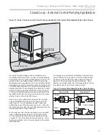
Page 21: ...losed position if it loses signal but still has 24V power running to it If the motorized modulating valve loses both signal from the DXM2 board AND 24V power it will remain in the same position it was in when it lost 24V power Note The Cv flow coefficient of the valve used in these units is DIFFERENT that the Cv of the valve used in the open loop unit It is not advisable for use in open loop applica...

Page 22: ... Systems Typical open loop piping is shown in Figure 20 Shut off valves should be included for ease of servicing Boiler drains or other valves should be tee d into the lines to allow acid flushing of the heat exchanger Shut off valves should be positioned to allow flow through the coax via the boiler drains without allowing flow into the piping system Schrader ports built into unit may be used to me...

Page 23: ...s forbid the use of sanitary sewer for disposal Consult your local building and zoning department to assure compliance in your area The pump should be sized to handle the home s domestic water load typically 5 9 gpm 23 41 l m plus the flow rate required for the heat pump Pump sizing and expansion tank must be chosen as complimentary items For example an expansion tank that is too small can cause p...

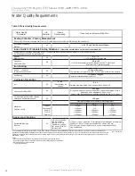
Page 24: ...0 ppm NR NR 304 SS 400 ppm 250 ppm 150 ppm 316 SS 1000 ppm 550 ppm 375 ppm Titanium 1000 ppm 550 ppm 375 ppm Erosion and Clogging Particulate Size and Erosion All 10 ppm of particles and a maximum velocity of 1 8 m s Filtered for maximum 841 micron 0 84 mm 20 mesh size 10 ppm 1 ppm sandfree for reinjection of particles and a maximum velocity of 1 8 m s Filtered for maximum 841 micron 0 84 mm 20 me...

Page 25: ...rolled by the lower element The upper 20 of the tank or 10 gallons will be maintained at 125 F controlled by the upper element Using a 125 F set point the HWG can heat the lower 40 gallons of water from 100 F to 125 F providing up to 8 330 btu s of heat Using the 150 F set point the HWG can heat the same 40 gallons of water from 100 F to 150 F and the remaining 10 gallons of water from 125 F to 15...

Page 26: ...ON SYSTEMS THAT EMPLOY AN APPROVED ANTI SCALD VALVE PART NUMBER AVAS4 AT THE HOT WATER STORAGE TANK WITH SUCH VALVE PROPERLY SET TO CONTROL WATER TEMPERATURES DISTRIBUTED TO ALL HOT WATER OUTLETS AT A TEMPERATURE LEVEL THAT PREVENTS SCALDING OR BURNS C H M WATER HEATER CHECK VALVE 8 MAX HOT WATER TO HOUSE ANTI SCALD VALVE ANTI SCALD VALVE PIPING CONNECTIONS COLD WATER SUPPLY Installation The HWG i...

Page 27: ...ge air from the HWG piping 2 Open a hot water faucet to vent air from the system until water flows from faucet turn off faucet Open valve 4 3 Depress the hot water tank pressure relief valve handle to ensure that there is no air remaining in the tank 4 Inspect all work for leaks 5 Before restoring power or fuel supply to the water heater adjust the temperature setting on the tank thermostat s to in...

Page 28: ...ical Code as well as all applicable local codes Refer to the unit electrical data for fuse sizes Consult wiring diagram for field connections that must be made by the installing or electrical contractor All final electrical connections must be made with a length of flexible conduit to minimize vibration and sound transmission to the building General Line Voltage Wiring Be sure the available power ...

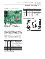
Page 29: ...lay Gnd NC 1 2 3 4 1 2 3 4 5 6 7 8 1 2 3 4 5 6 7 8 Accessory Relays Accessory Terminal The DXM2 controller includes two accessory relays ACC1 and ACC2 Each relay includes a normally open NO and a normally closed NC contact Accessory relays may be configured to operate as shown in Tables 8 and 9 Figure 26 Tranquility Low Voltage Field Wiring Table 9 Accessory Relay 2 Configuration Table 8 Accessory...

Page 30: ...e 28a iGate Communicating Thermostat Connection to DXM2 Control Thermostat Connection to DXM2 Control Compressor Compressor Stage 2 Reversing Valve Fan 24Vac Hot 24Vac Common Fault LED DXM2 Board Y1 Y2 W H O G R C AL1 Y1 Y2 W DH O G R C L iGate Thermostat ATC32U 24Vac Hot DXM2 24V Dehumidification Notes Auxiliary Heat 1 ECM automatic dehumidification mode operates with dehumidification airflows in...

Page 31: ...0Hz HFC 410A Rev 29 M ay 2 0 1 5 J DXM2 Wiring Diagram with Internal Flow Controller 96B0005N60 Part 1 of 2 This diagram includes typical wiring details but is not applicable to all units For specific unit wiring refer to the diagram or the units control panel ...

Page 32: ...32 Geothermal Heating and Cooling Tranquility 30 Digital TE Series IOM 60Hz HFC 410A R ev 29 May 2015J DXM2 Wiring Diagram with Internal Flow Controller 96B0005N60 Part 2 of 2 ...

Page 33: ... HFC 410A Rev 29 M ay 2 0 1 5 J DXM2 Wiring Diagram with Motorized Modulating WaterValve 96B0005N62 Part 1 of 2 This diagram includes typical wiring details but is not applicable to all units For specific unit wiring refer to the diagram or the units control panel ...

Page 34: ...34 Geothermal Heating and Cooling Tranquility 30 Digital TE Series IOM 60Hz HFC 410A R ev 29 May 2015J DXM2 Wiring Diagram with Motorized Modulating WaterValve 96B0005N62 Part 2 of 2 ...

Page 35: ...mits shown in Table 10 The blower operating modes include First Stage Cooling Y1 O Second Stage Cooling Y1 Y2 O First Stage Cooling in Dehumidification Mode Y1 O Dehumid Second Stage Cooling in Dehumidification Mode Y1 Y2 O Dehumid First Stage Heating Y1 Second Stage Heating Y1 Y2 Third Stage Auxiliary Heating Y1 Y2 W Emergency Heating W with no Y1 or Y2 Fan G with no Y1 Y2 or W It is necessary to...

Page 36: ...0 1100 850 550 1350 Maximum 1500 1100 1200 900 1500 1100 1500 1500 Minimum 900 600 825 550 900 600 450 1350 049 1 0 1 Default 1400 1050 1100 850 1500 1150 700 1500 Maximum 2000 1500 1600 1200 2000 1500 2000 2000 Minimum 1200 900 1100 825 1200 900 600 1350 064 0 7 1 Default 1750 1300 1400 1050 1875 1450 875 1875 Maximum 2300 1900 2000 1500 2300 1900 2300 2300 Minimum 1500 1100 1375 1000 1500 1100 7...

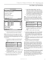
Page 37: ...AOM is shipped with each unit Thermostat compatibility It is strongly recommended that iGate communicating thermostat ATC32U or iGate configuration diagnostic tool ACDU be used with DXM2 control to ensure easy configuration monitoring and diagnostics in PLAIN English For example Airflow CAN NOT be configured without either the communicating thermostat or configuration diagnostic tool Field Hardwar...

Page 38: ...ation Accessory relays refer to DXM2 AOM for configuration Figure 31 LT1 Limit Setting Comp Relay 24Vdc EH1 EH2 P6 Off On JW3 c1 ay c2 ay CO RV RV LT2 LT2 P7 CC CCG CO S1 S2 12 1 4 Off On AO2 P11 Gnd T1 P10 T2 T2 T3 T3 T4 T4 T5 P9 T5 T6 T6 A0 1 A0 2 Off On S3 RV Relay CCH Relay 1 2 3 4 1 2 3 4 5 6 7 8 1 2 3 4 5 6 7 8 O1 Gnd DXM2 PCB JW3 LT1 jumper should be clipped for low temperature antifreeze o...

Page 39: ...uous operating conditions Minimum maximum limits are start up conditions to bring the building space up to occupancy temperatures Units are not designed to operate under these conditions on a regular basis 2 Voltage utilization complies with AHRI Standard 110 Cooling Heating Air Limits Min ambient air DB 45ºF 7ºC 39ºF 4ºC Rated ambient air DB 80 6ºF 27ºC 68ºF 20ºC Max ambient air DB 130ºF 54ºC 85º...

Page 40: ...fy that DXM2 field selection options are properly set Low voltage wiring is complete Blower CFM and Water T is set on communicating thermostats or diagnostic tool Service access panels are in place SYSTEM CHECKOUT System water temperature Check water temperature for proper range and also verify heating and cooling set points for proper operation System pH Check and adjust water pH if necessary to ...

Page 41: ...warm air delivery at the unit grille within a few minutes after the unit has begun to operate NOTE Units have a five minute time delay in the control circuit that can be bypassed on the DXM2 control board by placing the unit in the Test mode as shown in the unit IOM Check for normal air temperature rise of 20 F to 30 F heating mode c Verify that the compressor is on and that the water temperature ...

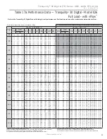
Page 42: ...ce the air coil should be cleaned before start up A 10 solution of dishwasher detergent and water is recommended Model GPM Pressure Drop psi 30ºF 50ºF 70ºF 90ºF 026 2 3 0 47 0 41 0 40 0 40 3 0 0 68 0 60 0 57 0 57 3 4 0 79 0 70 0 67 0 66 4 5 1 14 1 01 0 95 0 93 6 0 1 75 1 56 1 45 1 40 038 3 0 0 91 0 79 0 79 0 82 4 5 1 52 1 30 1 24 1 24 6 0 2 21 1 89 1 76 1 72 6 8 2 62 2 25 2 06 1 99 9 0 3 92 3 41 3...

Page 43: ...7 217 15 20 15 20 15 20 10 15 9 14 9 14 21 9 23 9 16 1 18 1 10 3 12 3 18 24 19 25 19 25 96 106 100 110 105 115 322 342 326 346 331 351 10 15 10 15 10 15 17 22 17 22 17 22 12 2 14 2 9 3 11 3 6 4 8 4 23 29 24 30 24 30 70 1 5 2 25 3 136 146 135 145 135 145 302 322 283 303 265 285 9 14 9 14 9 14 13 18 12 17 12 17 21 5 23 5 15 8 17 8 10 12 18 24 19 25 19 25 123 133 129 139 135 145 352 372 358 378 364 3...

Page 44: ...SIG Superheat Subcooling Water Temp Rise F Air Temp Drop F DB Suction Pressure PSIG Discharge Pressure PSIG Superheat Subcooling Water Temp Drop F Air Temp Rise F DB 30 1 5 2 25 3 61 71 65 75 68 78 292 312 296 316 300 320 11 16 11 16 10 15 13 18 14 19 15 20 7 2 9 2 5 4 7 4 3 5 5 5 19 25 20 26 21 27 50 1 5 2 25 3 131 141 130 140 129 139 210 230 205 225 200 220 10 15 11 16 13 18 12 17 12 17 12 17 18...

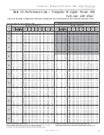
Page 45: ... 750 28 0 17 7 1 28 32 4 21 8 80 8 1 8 6 0 1 5 3 4 840 32 3 1 71 5 5 26 5 105 7 61 2 3 4 6 0 1 5 3 4 850 28 5 19 0 1 33 33 1 21 4 81 0 1 9 6 0 1 5 3 4 950 32 8 1 66 5 8 27 2 102 0 60 9 3 4 80 3 0 0 6 1 3 750 24 8 16 3 1 58 30 2 15 7 100 1 3 0 3 0 0 6 1 3 840 32 6 1 71 5 6 26 7 106 0 62 2 3 4 3 0 0 6 1 3 850 25 2 17 5 1 64 30 8 15 4 100 5 3 0 3 0 0 6 1 3 950 33 1 1 66 5 8 27 5 102 3 61 7 3 5 4 5 0 ...

Page 46: ...9 9 81 1 2 6 9 0 3 1 7 2 1250 48 3 2 50 5 7 39 8 105 8 61 2 4 7 80 4 5 1 2 2 9 1100 38 2 24 6 2 29 16 7 45 9 100 4 4 3 4 5 1 2 2 9 1100 48 0 2 59 5 4 39 2 110 4 62 6 4 6 4 5 1 2 2 9 1250 38 8 26 4 2 37 16 4 46 9 100 9 4 4 4 5 1 2 2 9 1250 48 8 2 51 5 7 40 2 106 1 62 1 4 7 6 8 2 0 4 7 1100 39 8 25 2 2 13 18 6 47 0 93 8 3 6 5 4 1 5 3 5 1100 49 5 2 63 5 5 40 5 111 7 65 0 4 8 6 8 2 0 4 7 1250 40 5 27 ...

Page 47: ... 0 80 5 2 9 12 0 3 3 7 6 1650 60 6 3 53 5 0 48 6 104 0 61 9 5 1 80 6 0 0 7 1 5 1360 48 1 31 8 3 07 15 7 58 6 99 5 4 5 6 0 0 7 1 5 1450 60 7 3 67 4 8 48 2 108 8 63 9 5 1 6 0 0 7 1 5 1550 49 0 34 2 3 18 15 4 59 8 99 9 4 6 6 0 0 7 1 5 1650 61 6 3 56 5 1 49 5 104 6 63 5 5 2 9 0 1 7 4 0 1360 50 1 32 7 2 87 17 5 59 9 93 3 3 8 6 5 0 8 1 9 1450 61 6 3 70 4 9 49 0 109 4 65 0 5 2 9 0 1 7 4 0 1550 51 0 35 1 ...

Page 48: ...44 20 6 82 8 81 0 3 5 15 0 4 1 9 5 2050 83 7 4 59 5 3 68 0 107 8 60 9 5 8 80 7 5 0 8 1 8 1630 62 5 44 1 4 05 15 4 76 2 100 3 5 5 7 5 0 8 1 8 1800 83 1 4 75 5 1 66 9 112 8 62 2 5 8 7 5 0 8 1 8 1850 63 5 47 5 4 19 15 1 77 8 100 8 5 6 7 5 0 8 1 8 2050 84 4 4 61 5 4 68 7 108 1 61 7 5 9 11 3 2 2 5 2 1630 65 1 45 1 3 78 17 2 77 9 93 8 4 7 9 3 1 4 3 3 1800 86 0 4 84 5 2 69 5 114 3 65 0 6 0 11 3 2 2 5 2 1...

Page 49: ... 2 80 7 5 5 17 0 5 4 12 4 2050 89 5 5 57 4 7 70 5 110 4 61 7 8 7 80 8 5 1 2 2 7 1630 68 4 44 7 4 72 14 5 84 4 99 9 8 2 8 5 1 2 2 7 1800 89 5 5 79 4 5 69 9 116 0 63 6 8 7 8 5 1 2 2 7 1850 69 5 48 1 4 89 14 2 86 2 100 3 8 4 8 5 1 2 2 7 2050 90 9 5 61 4 7 71 7 111 0 63 1 8 8 12 8 2 9 6 7 1630 71 2 45 8 4 40 16 2 86 1 93 5 7 1 9 5 1 5 3 6 1800 91 2 5 84 4 6 71 4 116 9 65 0 9 0 12 8 2 9 6 7 1850 72 4 4...

Page 50: ...rmance Filters should be inspected every month under normal operating conditions and be replaced when necessary Units should never be operated without a filter Washable high efficiency electrostatic filters when dirty can exhibit a very high pressure drop for the fan motor and reduce air flow resulting in poor performance It is especially important to provide consistent washing of these filters in t...

Page 51: ...4 20 116 240 8 0 43 47 116 6 4 04 117 242 6 0 42 48 118 4 3 89 118 244 4 0 41 49 120 2 3 74 119 246 2 0 40 50 122 0 3 60 120 248 0 0 39 51 123 8 3 47 121 249 8 0 38 52 125 6 3 34 122 251 6 0 37 53 127 4 3 22 123 253 4 0 36 54 129 2 3 10 General If operational difficulties are encountered perform the preliminary checks below before referring to the troubleshooting charts Verify that the unit is recei...

Page 52: ...s The Control Diagnostics menus allow the installer to see the current status of all DXM2 control switch inputs values of all temperature sensor inputs control voltage ECM blower internal flow center and proportional valve operating status and parameters Dipswitch Configuration The Dipswitch Configuration menus allow the installer to easily see the current DXM2 control configuration Fault History ...

Page 53: ... Unit Attempt to Start Did Unit Lockout at Start up Unit Short Cycles Only Fan Runs Only Compressor Runs Did unit lockout after a period of operation Does unit operate in cooling Unit is OK See Performance Troubleshooting for further help Check Main power see power problems Check fault code on communicating thermostat ATC32 or Configuration and Diagnostics Tool ACD01 Yes No No No No No Yes No Yes ...

Page 54: ...ity with hydrometer X Improper low temperature setting 30 F vs 10 F Clip LT1 jumper for antifreeze 10 F use X Water t emperature out of range Bring water temp within design parameters X X Bad thermistor Check temp and impedance correlation per chart LT2 Fault Code 5 Low Air Temperature X Reduced or no air flow Check for dirty air filter and clean or replace in cooling Check fan motor operation and...

Page 55: ...oo high of external static check static vs blower table Too much cold vent air bring entering air temp within design parameters No Fault Code Shown X X No compressor operation See Only Fan Operates X X Compressor overload Check and replace if necessary X X Control board Reset power and check operation Unit Short Cycles X X Dirty air filter Check and clean air filte r X X Unit in Test Mode Reset po...

Page 56: ...Check for dirty air filter and clean or replace in heating Check fan motor operation and airflow restrictions Too high of external static check static vs blower table X Reduced or no water flow Check pump operation or valve operation setting in cooling Check water flow adjust to proper flow rate X Inlet water too hot Check load loop sizing loop backfill ground moisture X Air temperature out of ran...

Page 57: ...ersing Valve Set for cooling demand and check 24VAC on RV coil If RV is stuck run high pressure up by reducing water flow and while operating engage and disengage RV coil voltage to push valve X Thermostat setup X Thermostat wiring Check O wiring at heat pump DXM2 requires call for compressor to get RV coil Click Modulating Valve Troubleshooting X Improper output setting Verify the AO 2 jumper is ...

Page 58: ...sure Drop 4b GPM Heat of Extraction Absorption or Heat of Rejection HE or HR Btuh Enter HE or HR Flow Rate GPM x Temp Diff deg F x Fluid Factor Refrigerant Analysis 5 Suction Temp 6 Suction Pressure 6a Saturation Temp 6b Superheat 7 Discharge Temp 8 Discharge Pressure 8a Saturation Temp 8b Subcooling 9 Liquid Line Temp 10 Return Air Temp 11 Supply Air Temp Temp Diff Voltage Compress Amps COMPRESSO...

Page 59: ...XDOL HG SHUVRQQHO 0ROG IXQJXV RU EDFWHULD GDPDJHV RUURVLRQ RU DEUDVLRQ RI WKH SURGXFW 3URGXFWV VXSSOLHG E RWKHUV 3URGXFWV ZKLFK KDYH EHHQ RSHUDWHG LQ D PDQQHU FRQWUDU WR 0 V SULQWHG LQVWUXFWLRQV 3URGXFWV ZKLFK KDYH LQVXI FLHQW SHUIRUPDQFH DV D UHVXOW RI LPSURSHU V VWHP GHVLJQ RU LPSURSHU DSSOLFDWLRQ LQVWDOODWLRQ RU XVH RI 0 V SURGXFWV RU OHFWULFLW RU IXHO FRVWV RU DQ LQFUHDVHV RU XQUHDOL HG VDYLQJ...

Page 60: ...argain between the parties but are merely ClimateMaster s opinion or commendation of its products The management system governing the manufacture of ClimateMaster s products is ISO 9001 2008 certified ClimateMaster Inc 2012 97B0045N04 7300 S W 44th Street Oklahoma City OK 73179 Phone 405 745 6000 Fax 405 745 6058 climatemaster com ISO 9001 2008 Certified Quality First Always Date Page Description ...

Reviews: