CLIMATEMASTER WATER-SOURCE HEAT PUMPS
Tranquility
®
(TRL) Series
R e v. : N o v e m b e r 1 1 , 2 0 2 1
C l i m a t e M a s t e r Wa t e r-S o u rc e H e a t P u m p s
56
Unit Start-Up Procedure
Unit Start-up Procedure
1. Turn the thermostat fan position to
“ON”. Blower should start.
2.
Balance air flow at registers.
3. Adjust all valves to their full open
positions. Turn on the line power to
all heat pumps.
4. Room temperature should be within
the minimum-maximum ranges
of Tables 7 and 8. During start-up
checks, loop water temperature
entering the heat pump should be
between 60°F [16°C] and 95°F [35°C].
5. Two factors determine the operating
limits of ClimateMaster heat pumps,
(a) return air temperature/flow, and
(b) water temperature/flow. When
any one of these factors is at a
minimum or maximum level, the
other factor must be at normal level
to ensure proper unit operation.
a. Adjust the unit thermostat to
the warmest setting. Place the
thermostat mode switch in the
“COOL” position. Slowly reduce
thermostat setting until the
compressor activates.
b. Check for cool air delivery at the
unit grille within a few minutes
after the unit has begun to
operate.
Note: Units have a five minute
time delay in the control
circuit that can be eliminated
on the CXM2 control board as
shown below in Figure 18. See
controls description for details.
c. Verify that the compressor is on
and that the water flow rate is
correct by measuring pressure
drop through the heat exchanger
using the P/T plugs & comparing
to Table 9. The unit must have
enough flow as per the flow
switch setpoint in order for the
compressor to start.
d. Check the elevation and
cleanliness of the condensate
lines. Dripping may be a sign
of a blocked line. Check that
the condensate trap is filled to
provide a water seal.
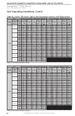
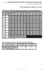
e. Refer to Table 7 and 8. Check
the temperature of both
entering and leaving water. If
temperature is within range,
proceed with the test. Verify
correct water flow by comparing
unit pressure drop across the
heat exchanger versus the data
in Table 9. Heat of rejection
(HR) can be calculated and
compared to submittal data
capacity pages. The formula for
HR for systems with water is as
follows:
HR (Btuh) = TD x GPM
x 500,where TD is the
temperature difference between
the entering and leaving water,
and GPM is the flow rate in U.S.
GPM, determined by comparing
the pressure drop across the
heat exchanger to Table 9. In S-I
units, the formula is as follows:
HR (kW) = TD x l/s x 4.18.
f. Check air temperature drop
across the air coil when
compressor is operating. Air
temperature drop should be
between 15
°
F and 25
°
F [8°C
and 14°C].
g. Turn thermostat to “OFF”
position. A hissing noise
indicates proper functioning of
the reversing valve.
6.
Allow five (5) minutes between
tests for pressure to equalize before
beginning heating test.
a. Adjust the thermostat to the
lowest setting. Place the
thermostat mode switch in the
“HEAT” position.


