background image

15

T H E   S M A R T   S O L U T I O N   F O R   E N E R G Y   E F F I C I E N C Y

Tr a n q u i l i t y

®

  ( T R )   S e r i e s

R e v. :   N o v e m b e r   2 ,   2 0 2 0

c l i m a t e m a s t e r. c o m

Water-Loop Heat Pump Applications

Commercial Water Loop Applications

Commercial systems typically include a number of units 

connected to a common piping system. Any unit plumbing 

maintenance work can introduce air into the piping system; 

therefore air elimination equipment is a major portion of the 

mechanical room plumbing. Consideration should be given 

to insulating the piping surfaces to avoid condensation. 

ClimateMaster recommends unit insulation any time the 

water temperature is expected to be below 60ºF (15.6ºC). 

Metal to plastic threaded joints should never be used due to 

their tendency to leak over time.

Teflon

®

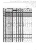
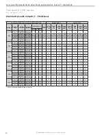
 tape thread sealant is recommended to minimize 

internal fouling of the heat exchanger. Do not over tighten 

connections and route piping so as not to interfere with 

service or maintenance access. Hose kits are available 

from ClimateMaster in different configurations as shown in 

Figure 12 for connection between the unit and the piping 

system. Depending upon selection, hose kits may include 

shut off valves, P/T plugs for performance measurement, 

high pressure stainless steel braided hose, “Y” type strainer 

with blow down valve, and/or “J” type swivel connection. 

Balancing valves and an external low pressure drop solenoid 

valve for use in variable speed pumping systems may also be 

included in the hose kit. 

The piping system should be flushed to remove dirt, piping 

chips, and other foreign material prior to operation (see 

“Piping System Cleaning and Flushing Procedures” in this 

manual). The flow rate is usually set between 2.25 and 3.5 

gpm per ton [2.9 and 4.5 l/m per kW] of cooling capacity. 

ClimateMaster recommends 3 gpm per ton [3.9 l/m per kW] 

for most applications of water loop heat pumps. To ensure 

proper maintenance and servicing, P/T ports are imperative 

for temperature and flow verification, as well as performance 

checks.

Water loop heat pump (cooling tower/boiler) systems 

typically utilize a common loop, maintained between 

60 - 90°F [16 - 32°C]. The use of a closed circuit evaporative 

cooling tower with a secondary heat exchanger between the 

tower and the water loop is recommended. If an open type 

cooling tower is used continuously, chemical treatment and 

filtering will be necessary.

Figure 12: Typical Water-Loop Application

3/8" [10mm] threaded rods

(by others)

Low Water Temperature Cutout Setting - CXM Control


When antifreeze is selected, the LT1 jumper (JW3) should be clipped to select the low temperature (antifreeze 10.0°F 

[-12.2°C]) setpoint and avoid nuisance faults (see “Low Water Temperature Cutout Selection” in this manual). 

Note: Low 

water temperature operation requires extended range equipment.

Summary of Contents for Tranquility TR Series

Page 1: ...al Power Wiring 30 Electrical Power Low Voltage Wiring 31 Electrical Low Voltage Wiring 32 Electrical Thermostat Wiring 33 Blower Performance Data 34 44 Blower Performance Data Hybrid 45 55 Constant Volume ECM Control 56 TR Series Wiring Diagram Matrix 57 Typical Wiring Diagram 58 63 CXM Controls 64 DXM2 Controls 65 68 Safety Features CXM and DXM2 Controls 69 70 ClimaDry Modulating Reheat Option 7...

Page 2: ......
Page 3: ...0 3 N 575 60 3 AVAILABLE VOLTAGES Option Supply Configuration Motor T B Top Back TRV TRH PSC PSC S Straight TRH PSC V TRV PSC Hi Static Y TRH Z TRH Top Back Straight K TRV TRV ECM CV P TRH W 1 2 3 DXM2 Controls Required for ECM CV Fan Motors TRH TRH TRH Top Back Straight Straight Top Back PSC Hi Static PSC Hi Static ECM CV ECM CV ECM CT ECM CT ECM CT CABINET INSULATION OPTION 1 A J K 2 C L M 3 E N...

Page 4: ... which is important but which is not hazard related WARNING The EarthPure Application and Service Manual should be read and understood before attempting to service refrigerant circuits with HFC 410A Inspection Upon receipt of the equipment carefully check the shipment against the bill of lading Make sure all units have been received Inspect the packaging of each unit and inspect each unit for dama...

Page 5: ...es before installing any of the system components Remove any dirt or debris found in or on these components Pre Installation Installation Operation and Maintenance instructions are provided with each unit Horizontal equipment is designed for installation above false ceiling or in a ceiling plenum Other unit configurations are typically installed in a mechanical room The installation site chosen sh...

Page 6: ... 20x20 20x20 20x20 20x20 24x24 24x24 28x28 28x28 Weight Operating lbs 110 112 121 163 168 184 192 213 228 283 298 Weight Packaged lbs 115 117 126 168 173 189 197 219 234 290 305 Horizontal Air Coil Dimensions H x W 10x15 10x15 10x15 16x22 16x22 16x22 16x22 20x25 20x25 20x35 20x35 Filter Standard 1 Throwaway 10x18 10x18 10x18 16x25 16x25 18x25 18x25 20x28 or 2 20x14 20x28 or 2 20x14 1 20x24 1 20x14...

Page 7: ... 12X10T Water Connection Size FPT All Other 1 2 1 2 1 2 1 2 1 2 3 4 3 4 3 4 3 4 1 1 Horizontal Air Coil Dimensions H x W 10x15 10x15 10x15 16x22 16x22 16x22 16x22 20x25 20x25 20x35 20x35 Filter Standard 1 Throwaway 10x18 10x18 10x18 16x25 16x25 18x25 18x25 20x28 or 2 20x14 20x28 or 2 20x14 1 20x24 1 20x14 1 20x24 1 20x14 Weight Operating Hybrid lbs 154 156 165 215 221 253 261 309 324 373 405 Weigh...

Page 8: ...d access panels Provide sufficient room to make water electrical and duct connection s If the unit is located in a confined space such as a closet provisions must be made for return air to freely enter the space by means of a louvered door etc Any access panel screws that would be difficult to remove after the unit is installed should be removed prior to setting the unit Refer to Figure 3 for an i...

Page 9: ...ing Loop Unit Power Disconnect Power Wiring Insulated supply duct with at least one 90 deg elbow to reduce air noise Return Air Supply Air Unit Hanger 3 8 10mm threaded rods Unit Power Flexible Duct Connector Figure 3 Typical Horizontal Unit Installation Optional Low Pressure Drop Water Control Valve can be internally mounted on some models Notice Installation Note Ducted Return Many horizontal WS...

Page 10: ... panel 2 Lift out the access panel and set aside Lift and rotate the discharge panel to the other position as shown being careful with the blower wiring 3 Check blower wire routing and connections for tension or contact with sheet metal edges Re route if necessary 4 Check refrigerant tubing for contact with other components 5 Reinstall top panel and screws noting that the location for some screws ...

Page 11: ...DRAIN LINE IT MUST BE LOCATED AFTER THE TRAP IN THE DIRECTION OF THE CONDENSATE FLOW Horizontal Installation Figure 6 Horizontal Condensate Connection CAUTION Ensure condensate line is pitched toward drain 1 8 inch per ft 11mm per m of run CAUTION Duct System Installation Proper duct sizing and design is critical to the performance of the unit The duct system should be designed to allow adequate a...

Page 12: ... electrical and duct connection s If the unit is located in a confined space such as a closet provisions must be made for return air to freely enter the space by means of a louvered door etc Any access panel screws that would be difficult to remove after the unit is installed should be removed prior to setting the unit Refer to Figures 7 and 8 for typical installation illustrations Refer to unit s...

Page 13: ...or proper drainage This connection must meet all local plumbing building codes Vertical units utilize a condensate hose inside the cabinet as a trapping loop therefore an external trap is not necessary Figure 10a shows typical condensate connections Figure 10b illustrates the internal trap for a typical vertical heat pump Each unit must be installed with its own individual vent where necessary and...

Page 14: ...ater temperature drops below the dew point insulation is required for ground loop applications in most climates Pipe joint compound is not necessary when Teflon thread tape is pre applied to hose assemblies or when flared end connections are used If pipe joint compound is preferred use compound only in small amounts on the external pipe threads of the fitting adapters Prevent sealant from reaching...

Page 15: ...d or J type swivel connection Balancing valves and an external low pressure drop solenoid valve for use in variable speed pumping systems may also be included in the hose kit The piping system should be flushed to remove dirt piping chips and other foreign material prior to operation see Piping System Cleaning and Flushing Procedures in this manual The flow rate is usually set between 2 25 and 3 5...

Page 16: ...eze however your local sales office should be consulted to determine the antifreeze best suited to your area Freeze protection should be maintained to 15 F 9 C below the lowest expected entering loop temperature For example if 30 F 1 C is the minimum expected entering loop temperature the leaving loop temperature would be 22 to 25 F 6 to 4 C and freeze protection should be at 15 F 10 C Calculation...

Page 17: ...RGY EFFI C I E NC Y Tranquilit y TR Ser i es Rev Novem b er 2 2020 climatemaster com Ground Loop Heat Pump Applications Figure 13 Typical Ground Loop Application High and Low Voltage Knockouts Vibration Isolation Pad To Thermostat ...

Page 18: ... or CPVC piping may cause failure of the PVC CPVC PVC CPVC piping should never be used as supply or return water piping with water source heat pump products containing HFC 410A as system failures and property damage may result WARNING Water Quality Standards Table 3 should be consulted for water quality requirements Scaling potential should be assessed using the pH Calcium hardness method If the p...

Page 19: ...flow of 1 5 to 2 gpm per ton 2 0 to 2 6 l m per kW is achieved A second method of flow control requires a flow control device mounted on the outlet of the water control valve The device is typically a brass fitting with an orifice of rubber or plastic material that is designed to allow a specified flow rate On occasion flow control devices may produce velocity noise that can be reduced by applying...

Page 20: ...er temperature Chloride Levels 10 C 24 C 38 C Copper Cupronickel 20ppm NR NR 150 ppm NR NR 304 SS 400 ppm 250 ppm 150 ppm 316 SS 1000 ppm 550 ppm 375 ppm Titanium 1000 ppm 550 ppm 375 ppm Erosion and Clogging Particulate Size and Erosion All 10 ppm of particles and a maximum velocity of 1 8 m s Filtered for maximum 841 micron 0 84 mm 20 mesh size 10 ppm 1 ppm sandfree for reinjection of particles ...

Page 21: ...d sound transmission to the building General Line Voltage Wiring Be sure the available power is the same voltage and phase shown on the unit serial plate Line and low voltage wiring must be done in accordance with local codes or the National Electric Code whichever is applicable WARNING To avoid possible injury or death due to electrical shock open the power supply disconnect switch and secure it ...

Page 22: ... 2 7 16 8 20 3 30A E 265 60 1 238 5 291 5 1 11 2 60 2 9 14 1 16 9 25A 2 9 14 1 16 9 25A F 460 60 3 414 506 1 4 2 28 1 6 5 8 6 9 15A 1 6 5 8 6 9 15A H 208 230 60 3 187 2 253 1 8 9 58 2 7 11 6 13 8 20A 2 7 11 6 13 8 20A 036 G 208 230 60 1 187 2 253 1 16 7 79 2 7 19 4 23 6 40A 2 7 19 4 23 6 40A E 265 60 1 238 5 291 5 1 13 5 72 2 0 15 5 18 9 30A 2 9 16 4 19 8 30A F 460 60 3 414 506 1 5 8 38 1 2 7 0 8 ...

Page 23: ...3 6 28 0 7 1 4 5 7 6 6 15A 1 6 5 9 6 8 15A H 208 230 60 3 187 2 253 1 7 7 55 4 0 8 1 5 10 0 11 9 15A 2 7 11 2 13 1 20A 030 G 208 230 60 1 187 2 253 1 14 1 73 0 8 2 7 17 6 21 1 35A 2 7 17 6 21 1 35A E 265 60 1 238 5 291 5 1 11 2 60 0 7 2 9 14 8 17 6 25A 2 9 14 8 17 6 25A F 460 60 3 414 506 1 4 2 28 0 7 1 6 6 5 7 6 15A 1 6 6 5 7 6 15A H 208 230 60 3 187 2 253 1 8 9 58 0 8 2 7 12 4 14 6 20A 2 7 12 4 ...

Page 24: ...2 28 0 7 1 6 6 5 7 6 15A 1 6 6 5 7 6 15A H 208 230 60 3 187 2 253 1 8 9 58 0 8 2 7 12 4 14 6 20A 2 7 12 4 14 6 20A 036 G 208 230 60 1 187 2 253 1 16 7 79 0 8 2 7 20 2 24 4 40A 2 7 20 2 24 4 40A E 265 60 1 238 5 291 5 1 13 5 72 0 7 2 0 16 2 19 6 30A 2 9 17 1 20 5 30A F 460 60 3 414 506 1 5 8 38 0 7 1 2 7 7 9 2 15A 1 6 8 1 9 6 15A H 208 230 60 3 187 2 253 1 10 4 73 0 8 2 7 13 9 16 5 25A 2 7 13 9 16 ...

Page 25: ...15 2 20A F 460 60 3 414 506 1 3 6 28 3 2 6 8 7 7 15A 1 1 4 7 5 6 15A H 208 230 60 3 187 2 253 1 7 7 55 4 3 9 11 6 13 5 20A 3 9 11 6 13 5 20A 030 G 208 230 60 1 187 2 253 1 14 1 73 3 9 18 0 21 5 35A 3 9 18 0 21 5 35A E 265 60 1 238 5 291 5 1 11 2 60 3 2 14 4 17 2 25A 3 2 14 4 17 2 25A F 460 60 3 414 506 1 4 2 28 3 2 7 4 8 5 15A 1 1 5 3 6 4 15A H 208 230 60 3 187 2 253 1 8 9 58 3 9 12 8 15 0 20A 3 9...

Page 26: ...5 9 25A 3 2 13 5 15 9 25A F 460 60 3 414 506 1 3 6 28 0 7 3 2 7 5 8 4 15A 1 1 5 4 6 3 15A H 208 230 60 3 187 2 253 1 7 7 55 4 0 8 3 9 12 4 14 3 20A 3 9 12 4 14 3 20A 030 G 208 230 60 1 187 2 253 1 14 1 73 0 8 3 9 18 8 22 3 35A 3 9 18 8 22 3 35A E 265 60 1 238 5 291 5 1 11 2 60 0 7 3 2 15 1 17 9 25A 3 2 15 1 17 9 25A F 460 60 3 414 506 1 4 2 28 0 7 3 2 8 1 9 2 15A 1 1 6 0 7 1 15A H 208 230 60 3 187...

Page 27: ...5A 1 1 6 0 7 1 15A H 208 230 60 3 187 2 253 1 8 9 58 0 8 3 9 13 6 15 8 20A 3 9 13 6 15 8 25A 036 G 208 230 60 1 187 2 253 1 16 7 79 0 8 6 0 23 5 27 7 40A 6 0 23 5 27 7 40A E 265 60 1 238 5 291 5 1 13 5 72 0 7 4 8 19 0 22 4 35A 3 9 18 1 21 5 30A F 460 60 3 414 506 1 5 8 38 0 7 4 8 11 3 12 8 15A 1 5 8 0 9 5 15A H 208 230 60 3 187 2 253 1 10 4 73 0 8 6 0 17 2 19 8 25A 6 0 17 2 19 8 30A 042 G 208 230 ...

Page 28: ... 9 6 54 3 2 12 8 15 2 20A 3 2 12 8 15 2 20A F 460 60 3 414 506 1 3 6 28 3 2 6 8 7 7 15A 1 1 4 7 5 6 15A H 208 230 60 3 187 2 253 1 7 7 55 4 3 9 11 6 13 5 20A 3 9 11 6 13 5 20A 030 G 208 230 60 1 187 2 253 1 14 1 73 6 0 20 1 23 6 35A 6 0 20 1 23 6 35A E 265 60 1 238 5 291 5 1 11 2 60 4 7 15 9 18 7 25A 3 9 15 1 17 9 25A F 460 60 3 414 506 1 4 2 28 4 8 9 0 10 1 15A 1 5 5 7 6 8 15A H 208 230 60 3 187 ...

Page 29: ...12 8 15 9 25A 3 2 12 8 15 9 25A F 460 60 3 414 506 1 3 6 28 0 7 3 2 6 8 8 4 15A 1 1 4 7 6 3 15A H 208 230 60 3 187 2 253 1 7 7 55 4 0 8 3 9 11 6 14 3 20A 3 9 11 6 14 3 20A 030 G 208 230 60 1 187 2 253 1 14 1 73 0 8 6 0 20 1 24 4 35A 6 0 20 1 24 4 35A E 265 60 1 238 5 291 5 1 11 2 60 0 7 4 7 15 9 19 4 30A 3 9 15 1 18 6 25A F 460 60 3 414 506 1 4 2 28 0 7 4 8 9 0 10 8 15A 1 5 5 7 7 5 15A H 208 230 6...

Page 30: ... data or engineering design guide for specific unit airflow tables Typical unit design delivers rated airflow at nominal static 0 15 in w g 37Pa on medium speed and rated airflow at a higher static 0 4 to 0 5 in w g 100 to 125 Pa on high speed for applications where higher static is required Low speed will deliver approximately 85 of rated airflow at 0 10 in w g 25 Pa An optional high static blowe...

Page 31: ...the coaxial heat exchanger and expansion device TXV Therefore LT1 is sensing refrigerant temperature not water temperature which is a better indication of how water flow rate temperature is affecting the refrigeration circuit The factory setting for LT1 is for systems using water 30 F 1 1 C refrigerant temperature In low water temperature extended range applications with antifreeze most ground loo...

Page 32: ...s valves Slow closing valves take approximately 60 seconds to open very little water will flow before 45 seconds Once fully open an end switch allows the compressor to be energized Only relay or triac based electronic thermostats should be used with slow closing valves When wired as shown the slow closing valve will operate properly with the following notations 1 The valve will remain open during ...

Page 33: ...walls The wire access hole behind the thermostat may in certain cases need to be sealed to prevent erroneous temperature measurement Position the thermostat back plate against the wall so that it appears level and so the thermostat wires protrude through the middle of the back plate Mark the position of the back plate mounting holes and drill holes with a 3 16 5mm bit Install supplied anchors and ...

Page 34: ...50 Default CFM RPM 983 1102 1211 1319 1419 1516 1610 1708 1783 1817 Power W 29 35 41 47 53 60 67 76 81 77 CFM 225 225 225 225 225 225 225 225 225 225 Maximum CFM RPM 1053 1162 1265 1366 1462 1553 1648 1733 1802 1817 Power W 35 41 47 53 60 67 76 84 88 78 CFM 250 250 250 250 250 250 250 250 250 250 See ECM control section for details on setting airflow Airflow is controlled within 5 up to the Max ES...

Page 35: ...225 225 225 225 225 225 225 Default CFM RPM 1209 1326 1430 1535 1635 1732 1792 1801 1811 Power W 49 58 67 77 88 100 105 95 88 CFM 325 325 325 325 325 325 325 325 325 Maximum CFM RPM 1691 1753 1765 1769 1778 1784 1793 1803 1813 Power W 126 134 131 125 119 118 105 98 90 CFM 375 375 375 375 375 375 375 375 375 See ECM control section for details on setting airflow Airflow is controlled within 5 up to...

Page 36: ...m CFM RPM 1258 1368 1464 1555 1635 1718 1793 1830 Power W 55 64 73 81 90 99 107 106 CFM 300 300 300 300 300 300 300 300 Default CFM RPM 1598 1672 1743 1813 1831 1845 1859 1875 Power W 105 115 125 135 132 127 123 118 CFM 380 380 380 380 380 380 380 380 Maximum CFM RPM 1798 1823 1834 1844 1858 1872 1886 1901 1920 Power W 147 149 146 143 139 134 130 126 120 CFM 415 415 415 415 415 415 415 415 415 See...

Page 37: ...488 444 402 525 375 ECM Constant Volume Minimum CFM RPM 617 741 848 945 1028 1103 1171 Power W 36 52 68 84 99 114 129 CFM 375 375 375 375 375 375 375 Default CFM RPM 661 767 859 944 1028 1107 1179 1247 Power W 55 74 90 108 127 147 166 186 CFM 525 525 525 525 525 525 525 525 Maximum CFM RPM 586 695 795 882 963 1038 1111 1180 1248 1312 Power W 54 73 93 112 132 152 173 194 216 238 CFM 625 625 625 625...

Page 38: ...FM 854 848 820 791 754 724 711 683 655 625 600 450 ECM Constant Volume Minimum CFM RPM 1096 1179 1275 1361 Power W 111 132 157 180 CFM 450 450 450 450 Default CFM RPM 847 918 971 1095 1208 1297 1360 1418 1467 Power W 85 101 113 145 178 206 228 248 266 CFM 600 600 600 600 600 600 600 600 600 Maximum CFM RPM 1036 1080 1131 1172 1213 1317 1406 1494 Power W 157 171 186 200 214 251 286 323 CFM 750 750 ...

Page 39: ... CFM RPM 882 943 1002 1059 1114 1168 1220 1271 1319 1366 Power W 145 165 185 205 225 245 266 285 306 326 CFM 800 800 800 800 800 800 800 800 800 800 Maximum CFM RPM 1077 1122 1162 1200 1233 1263 1288 1310 1329 1343 Power W 284 300 315 332 351 364 379 396 412 428 CFM 1000 1000 1000 1000 1000 1000 1000 1000 1000 1000 See ECM control section for details on setting airflow Airflow is controlled within...

Page 40: ... W 71 89 108 127 145 162 181 199 217 235 CFM 750 750 750 750 750 750 750 750 750 750 Default CFM RPM 1131 1177 1218 1252 1295 1337 1381 1415 Power W 251 274 296 315 337 362 387 407 CFM 1000 1000 1000 1000 1000 1000 1000 1000 Maximum CFM RPM 1260 1299 1334 1373 1403 Power W 388 410 431 453 471 CFM 1150 1150 1150 1150 1150 See ECM control section for details on setting airflow Airflow is controlled ...

Page 41: ...3 5 RPM 1193 1228 1265 1295 1323 1358 1392 1419 Power W 499 510 523 524 521 519 516 514 CFM 1485 1460 1434 1396 1347 1295 1240 1194 1150 900 ECM Constant Volume Minimum CFM RPM 682 788 898 976 1043 1107 1170 1230 1297 1371 Power W 105 132 164 188 211 233 257 280 307 339 CFM 900 900 900 900 900 900 900 900 900 900 Default CFM RPM 830 895 961 1054 1145 1209 1267 1321 1371 1419 Power W 205 232 261 30...

Page 42: ...1 1623 1601 1577 1548 1519 1488 1455 1423 1355 5 RPM 1317 1372 1392 1412 1436 1469 1500 1504 Power W 756 775 776 774 772 768 765 679 CFM 1743 1717 1688 1645 1596 1541 1490 1352 1400 1050 ECM Constant Volume Minimum CFM RPM 786 855 920 985 1059 1125 1186 1240 1292 1346 Power W 154 177 200 224 252 280 306 331 355 383 CFM 1050 1050 1050 1050 1050 1050 1050 1050 1050 1050 Default CFM RPM 997 1042 1094...

Page 43: ...685 1647 1608 1560 1382 5 RPM 1078 1113 1145 1174 1200 1213 1200 Power W 649 667 684 698 714 695 588 CFM 1993 1956 1919 1886 1854 1784 1588 1500 1200 ECM Constant Volume Minimum CFM RPM 703 766 827 886 943 998 1051 1102 1150 1196 Power W 174 205 237 269 302 336 371 407 444 482 CFM 1200 1200 1200 1200 1200 1200 1200 1200 1200 1200 Default CFM RPM 833 884 932 986 1043 1089 1137 1191 1242 1293 Power ...

Page 44: ... 832 848 864 883 900 CFM 2235 2198 2163 2130 2094 2061 2019 1977 1939 5 RPM 1003 1025 1050 1074 1099 1122 1147 1166 1194 1209 Power W 866 881 899 916 934 951 970 977 973 969 CFM 2322 2290 2253 2219 2188 2152 2120 2083 2013 1940 1950 1500 ECM Constant Volume Minimum CFM RPM 705 773 836 894 949 998 1044 1085 1121 1153 Power W 246 301 354 405 453 500 544 587 627 665 CFM 1500 1500 1500 1500 1500 1500 ...

Page 45: ...6 78 80 CFM 244 232 220 210 195 225 150 ECM Constant Volume Minimum CFM RPM 926 1027 1124 1231 1343 1434 1531 1638 1740 1841 Power W 20 25 30 35 40 45 50 55 60 65 CFM 150 150 150 150 150 150 150 150 150 150 Default CFM RPM 1029 1137 1248 1353 1456 1569 1680 1785 1893 2001 Power W 40 45 50 55 60 65 70 75 80 85 CFM 225 225 225 225 225 225 225 225 225 225 Maximum CFM RPM 1084 1185 1285 1386 1487 1587...

Page 46: ...3 CFM 374 358 348 338 328 321 302 287 256 223 4 RPM 1819 1834 1822 1827 1849 Power W 130 120 110 100 90 CFM 372 353 300 265 231 325 225 ECM Constant Volume Minimum CFM RPM 976 1080 1182 1290 1401 1499 1601 1709 1814 1918 Power W 33 41 50 56 60 71 80 86 93 101 CFM 225 225 225 225 225 225 225 225 225 225 Default CFM RPM 1684 1714 1753 1754 1765 1795 Power W 110 109 110 104 100 99 CFM 325 325 325 325...

Page 47: ... 117 110 CFM 445 432 416 391 376 354 324 400 300 ECM Constant Volume Minimum CFM RPM 1318 1404 1487 1576 1667 1748 1831 1920 2006 2092 Power W 50 60 70 80 90 100 110 120 130 140 CFM 300 300 300 300 300 300 300 300 300 300 Default CFM RPM 1648 1716 1787 1852 1913 1988 2059 2124 2192 2260 Power W 97 109 120 134 150 159 170 184 197 209 CFM 400 400 400 400 400 400 400 400 400 400 Maximum CFM RPM 2023 ...

Page 48: ...602 557 493 454 417 5 RPM 1252 1317 1391 1438 Power W 191 198 208 215 CFM 626 577 519 480 525 375 ECM Constant Volume Minimum CFM RPM 723 793 813 934 1004 1074 1161 Power W 27 44 62 80 97 115 133 CFM 375 375 375 375 375 375 375 Default CFM RPM 756 830 872 976 1049 1123 1207 1269 1343 Power W 53 76 99 121 143 166 189 211 234 CFM 525 525 525 525 525 525 525 525 525 Maximum CFM RPM 777 851 924 1000 1...

Page 49: ... 756 726 691 653 597 543 507 5 RPM 1288 1359 1442 1532 Power W 236 248 262 276 CFM 737 702 659 593 600 450 ECM Constant Volume Minimum CFM RPM 682 772 860 950 1041 1128 1216 1306 1395 1484 Power W 46 69 93 115 136 161 185 207 230 253 CFM 450 450 450 450 450 450 450 450 450 450 Default CFM RPM 752 829 904 982 1062 1136 1211 1289 1366 1442 Power W 75 99 122 145 167 191 215 238 261 284 CFM 600 600 60...

Page 50: ... 311 322 333 345 CFM 1004 980 954 925 896 867 838 807 5 RPM 1314 1357 1399 1444 Power W 380 391 403 416 CFM 1004 977 950 923 800 600 ECM Constant Volume Minimum CFM RPM 766 833 899 967 1037 1101 1167 1235 1302 1369 Power W 80 99 118 136 154 174 193 211 229 248 CFM 600 600 600 600 600 600 600 600 600 600 Default CFM RPM 890 950 1006 1071 1141 1192 1247 1312 1372 1433 Power W 148 172 194 218 244 265...

Page 51: ...400 Power W 494 507 518 530 541 551 561 571 580 CFM 1244 1219 1198 1176 1152 1134 1116 1098 1082 5 RPM 1434 1458 1477 Power W 711 722 723 CFM 1246 1228 1200 1000 750 ECM Constant Volume Minimum CFM RPM 841 892 942 994 1048 1096 1146 1198 1249 1300 Power W 160 184 208 232 256 280 304 328 352 375 CFM 750 750 750 750 750 750 750 750 750 750 Default CFM RPM 1027 1070 1112 1156 1202 1243 1285 1330 1373...

Page 52: ...96 CFM 1398 1374 1354 1329 1304 1278 1252 1226 1201 1172 5 RPM 1046 1079 1107 1139 1170 1186 1226 1258 1287 1318 Power W 474 487 498 511 530 527 544 557 570 584 CFM 1503 1480 1458 1438 1428 1388 1361 1338 1313 1290 1150 900 ECM Constant Volume Minimum CFM RPM 728 784 838 895 953 1006 1060 1117 Power W 126 148 171 193 215 238 261 284 CFM 900 900 900 900 900 900 900 900 Default CFM RPM 883 931 976 1...

Page 53: ...1314 1340 1367 1395 Power W 611 625 638 649 661 675 688 700 714 728 CFM 1679 1655 1628 1604 1577 1553 1529 1503 1476 1450 5 RPM 1271 1292 1309 1327 1346 1364 1385 1405 Power W 753 761 759 757 756 754 753 751 CFM 1736 1709 1672 1634 1595 1558 1514 1472 1400 1050 ECM Constant Volume Minimum CFM RPM 816 870 921 976 1034 Power W 176 204 232 260 288 CFM 1050 1050 1050 1050 1050 Default CFM RPM 986 1032...

Page 54: ... 1697 1651 1609 1565 1521 5 RPM 1103 1129 1155 1181 1207 1232 Power W 831 848 866 885 904 921 CFM 1963 1916 1872 1830 1791 1755 1500 1200 ECM Constant Volume Minimum CFM RPM 724 774 824 875 928 977 1026 1078 1129 1179 Power W 192 231 272 310 348 389 429 468 508 547 CFM 1200 1200 1200 1200 1200 1200 1200 1200 1200 1200 Default CFM RPM 883 925 965 1008 1052 1091 1131 1174 1216 1257 Power W 408 453 4...

Page 55: ...755 4 RPM 1049 1073 1099 1125 1149 1169 1189 1208 1228 1248 Power W 897 915 934 952 963 959 955 952 948 946 CFM 2224 2186 2145 2107 2055 1988 1926 1864 1804 1745 5 RPM Power W CFM 1950 1500 ECM Constant Volume Minimum CFM RPM 814 862 908 956 1006 1051 1097 1145 1192 1240 Power W 324 376 428 479 530 582 634 685 736 788 CFM 1500 1500 1500 1500 1500 1500 1500 1500 1500 1500 Default CFM RPM 1046 1072 ...

Page 56: ...rpm to a full stop at the end of each blower cycle This creates a much quieter end to each blower cycle and adds overall unit efficiency The ramp down feature is eliminated during an ESD Emergency Shut Down situation When the DXM2 ESD input is activated the blower and all other control outputs are immediately de activated The ramp down feature also known as the heating or cooling Off Delay is fiel...

Page 57: ...523N03 96B0523N13 96B0523N23 96B0523N33 CXM Constant Torque ECM 96B0506N01 96B0506N11 96B0506N21 96B0506N31 CXM LON 96B0506N02 96B0506N12 96B0506N22 96B0506N32 CXM MPC 96B0506N03 96B0506N13 96B0506N23 96B0506N33 DXM2 96B0527N01 96B0527N11 96B0527N21 96B0527N31 DXM2 LON 96B0527N02 96B0527N12 96B0527N22 96B0527N32 DXM2 MPC 96B0527N03 96B0527N13 96B0527N23 96B0527N33 DXM2 Hydronic Heating Constant Vo...

Page 58: ...ATEM ASTER WATER SOURCE HEAT PUMPS Tra n quilit y TR Series Rev Novemb er 2 2020 ClimateMaster Water Source Heat Pumps Typical Wiring Diagram Single Phase TR Units Sizes 015 060 with CXM Control ECM CT Fan Motor ...

Page 59: ...E SMART SOLUTION FOR ENERGY EFFI C I E NC Y Tranquilit y TR Ser i es Rev Novem b er 2 2020 climatemaster com Typical Wiring Diagram Single Phase TR Units Sizes 015 060 with DXM2 Control and ECM CV Fan Motor ...

Page 60: ...TEM ASTER WATER SOURCE HEAT PUMPS Tra n quilit y TR Series Rev Novemb er 2 2020 ClimateMaster Water Source Heat Pumps Typical Wiring Diagram Single Phase TR Units Sizes 015 060 with CXM Control and PSC Fan Motor ...

Page 61: ...THE SMART SOLUTION FOR ENERGY EFFI C I E NC Y Tranquilit y TR Ser i es Rev Novem b er 2 2020 climatemaster com Typical Wiring Diagram Three Phase TR Units Sizes 024 060 with DXM2 Control and PSC Fan Motor ...

Page 62: ...STER WATER SOURCE HEAT PUMPS Tra n quilit y TR Series Rev Novemb er 2 2020 ClimateMaster Water Source Heat Pumps Typical Wiring Diagram Single Phase TR Units Sizes 024 060 with DXM2 Control PSC Fan Motor and ClimaDry ...

Page 63: ... THE SMART SOLUTION FOR ENERGY EFFI C I E NC Y Tranquilit y TR Ser i es Rev Novem b er 2 2020 climatemaster com Single Phase TR Unit Sizes 015 060 with CXM Controller CT ECM Fan Motor and Hydronic Heating ...

Page 64: ...eld configuration options jumper wires should be clipped ONLY when power is removed from the CXM control Water coil low temperature limit setting Jumper 3 JW3 LT1 Low Temp provides field selection of temperature limit setting for LT1 of 30 F or 10 F 1 F or 12 C refrigerant temperature Not Clipped 30 F 1 C Clipped 10 F 12 C Air coil low temperature limit setting Jumper 2 JW2 LT2 Low Temp provides f...

Page 65: ... DIP Switches Note In the following field configuration options DIP switches should only be changed when power is removed from the DXM2 control DIP Package 1 S1 DIP Package 1 has 8 switches and provides the following setup selections 1 1 Unit Performance Sentinel UPS disable DIP Switch 1 1 provides field selection to disable the UPS feature On Enabled Off Disabled 1 2 Compressor relay staging oper...

Page 66: ...e between the coaxial heat exchanger and the expansion device TXV Therefore the 50 F 10 C setting is not 50 F 10 C water but approximately 60 F 16 C EWT On 50 F 10 C Off 40 F 16 C DIP Package 2 S2 A combination of dip switches 2 1 2 2 2 3 and 2 4 2 5 2 6 deliver configuration of ACC1 and ACC2 relay options respectively See Table 5b for description and functionality 2 7 Auto dehumidification fan mo...

Page 67: ...ED and Status Operation with Test Mode Active Fault LED Red Status LED Green Alarm Relay No Fault Since Power Up In Memory Flashing Code 1 Cycling Code 1 High Pressure Fault In Memory Flashing Code 2 Cycling Code 2 Low Pressure Fault In Memory Flashing Code 3 Cycling Code 3 Low Temperature Protection 1 In Fault Memory Flashing Code 4 Cycling Code 4 Low Temperature Protection 2 In Fault Memory Flas...

Page 68: ...anti short cycle delay at power up The first time after power up that there is a call for compressor the compressor will follow a 5 to 80 second random start delay After the random start delay and anti short cycle delay the compressor relay will be energized On all subsequent compressor calls the random start delay is omitted P1 Alarm Relay Comp Relay O Y1 Y2 W G C R AL1 24Vdc EH1 EH2 P6 R C Off O...

Page 69: ...sec pause 2 quick flashes 10 sec pause etc Low pressure switch The low pressure switch must be open and remain open for 30 continuous seconds during on cycle to be recognized as a low pressure fault If the low pressure switch is open for 30 seconds prior to compressor power up it will be considered a low pressure loss of charge fault The low pressure switch input is bypassed for the initial 120 se...

Page 70: ...hut down the unit The green status light will flash code 3 when the unit is in ESD mode ESD mode code 3 green status LED Diagnostic Features The LED on the CXM board advises the technician of the current status of the CXM control The LED can display either the current CXM mode or the last fault in memory if in test mode If there is no fault in memory the LED will flash Code 1 when in test mode The...

Page 71: ...tinue to run in 1st Stage Cooling until the 1st Stage Cooling call is removed or satisfied shutting down the unit Note Not all units have two stage cooling functionality e g GC series units 1st Stage Heating A simultaneous call from G and Y1 to the G and Y1 terminals of the DXM2 control board will bring the unit on in 1st Stage Heating 2nd Stage Heating A simultaneous call from G Y1 and Y2 to the ...

Page 72: ...Special flow regulation water regulating valve is not required for low EWT conditions However below 55 F 13 C supply air temperatures may not be maintained at 72 F 22 C because the cooling capacity exceeds the reheat coil capacity at low water temperatures Below 55 F 13 C essentially all water is diverted to the reheat coil no heat of rejection to the building loop Although the ClimaDry option wil...

Page 73: ... Full load operation for dual capacity units 4 ON OFF Either ON or OFF Mode Input Output O G Y1 Y23 H O G Y1 Y23 Reheat No Demand ON OFF OFF OFF OFF OFF ON OFF OFF OFF OFF OFF Fan Only ON OFF ON OFF OFF OFF ON OFF ON OFF OFF OFF Cooling 1st Stage ON ON ON OFF OFF ON ON ON OFF OFF Cooling 2nd Stage ON ON ON ON OFF ON ON ON ON OFF Cooling Dehumidistat1 ON ON ON ON OFF ON ON ON ON ON OFF OFF Dehumidi...

Page 74: ...F 18 13ºC Cooling Heating Cooling Heating 45ºF 7ºC 39ºF 4ºC 45ºF 7ºC 39ºF 4ºC 0 6ºF 27ºC 68ºF 20ºC 80 6ºF 27ºC 68ºF 20ºC 10ºF 43ºC 85ºF 29ºC 110ºF 43ºC 85ºF 29ºC 60ºF 21 16ºC 60ºF 16ºC 70 60ºF 21 16ºC 60ºF 16ºC 66 2ºF 27 19ºC 68ºF 20ºC 80 6 66 2ºF 27 19ºC 68ºF 20ºC 75ºF 35 24ºC 80ºF 27ºC 95 75ºF 35 24ºC 80ºF 27ºC 30ºF 1ºC 20ºF 7ºC 50ºF 10ºC 50ºF 10ºC 10ºF 10 43ºC 30 70ºF 1 to 21ºC 60 90ºF 15 to 32...

Page 75: ...the system and add trisodium phosphate in a proportion of approximately one pound per 150 gallons 8 kg per 1000 l of water or other equivalent approved cleaning agent Reset the boiler to raise the loop temperature to 100 F 38 C Circulate the solution for a minimum of 8 to 24 hours At the end of this period shut off the circulating pump and drain the solution Repeat system cleaning if desired 8 Whe...

Page 76: ...inal of the DXM2 controller as shown in figure 1 to energize the modulating three way dehumidi fication valve Once energized the valve will take 45 75 seconds to fully shift Continue flushing during this time After the valve has completed its shift use the air bleed from the top of the reheat coil to purge air from the coil De energize the valve by removing the red wire from the ACC1 NC terminal o...

Page 77: ...oses and fittings see table 3 System flushing Verify that all hoses are connected end to end when flushing to ensure that debris bypasses the unit heat exchanger water valves and other components Water used in the system must be potable quality initially and clean of dirt piping slag and strong chemical cleaning agents Verify that all air is purged from the system Air in the system can cause poor ...

Page 78: ... by comparing the pressure drop across the heat exchanger to table 7 In S I units the formula is as follows HR kW TD x l s x 4 18 f Check air temperature drop across the air coil when compressor is operating Air temperature drop should be between 15 F and 25 F 8 C and 14 C g Turn thermostat to OFF position A hissing noise indicates proper functioning of the reversing valve 6 Allow five 5 minutes b...

Page 79: ...3 8 0 622 1 437 5 6 1 351 3 121 036 4 5 0 872 2 015 6 8 1 992 4 602 042 5 3 1 210 2 796 7 9 2 689 6 212 048 6 0 1 551 3 583 9 0 3 490 8 062 060 7 5 1 491 3 445 11 3 3 385 7 820 Model U S GPM l s Pressure Drop psi kPa 30 F 1 C 50 F 10 C 70 F 21 C 90 F 32 C TR 006 0 75 0 05 0 5 3 7 0 3 2 3 0 2 1 6 0 2 1 6 1 1 0 07 0 8 5 3 0 5 3 5 0 4 2 7 0 3 2 2 1 5 0 09 1 3 8 8 0 9 6 1 0 7 4 8 0 6 4 0 TR 009 1 1 0 ...

Page 80: ... Based on 15 Methanol antifreeze solution 009 Full Load Cooling without HWG active Full Load Heating without HWG active Entering Water Temp F Water Flow GPM ton Suction Pressure PSIG Discharge Pressure PSIG Superheat Subcooling Water Temp Rise F Air Temp Drop F DB Suction Pressure PSIG Discharge Pressure PSIG Superheat Subcooling Water Temp Drop F Air Temp Rise F DB 30 1 5 2 25 3 113 123 110 120 1...

Page 81: ... 23 50 1 5 2 25 3 128 138 128 138 128 138 194 214 180 200 166 186 11 14 11 14 11 14 9 14 7 12 7 12 17 9 19 9 13 7 15 7 9 4 11 4 18 24 19 25 19 25 102 112 106 116 110 120 312 332 316 336 321 341 10 15 10 15 10 15 2 6 2 6 2 6 9 9 11 9 7 4 9 4 4 9 6 9 22 28 23 29 23 29 70 1 5 2 25 3 136 146 136 146 136 146 289 309 275 295 261 281 7 12 7 12 7 12 9 14 7 12 6 11 17 4 19 4 15 3 17 3 8 8 10 8 17 23 18 24 ...

Page 82: ...5 7 7 7 3 7 5 7 19 27 19 27 20 28 50 1 5 2 25 3 121 131 120 130 120 130 249 269 231 251 214 234 12 17 12 17 12 17 9 14 8 13 8 13 19 4 21 4 14 4 16 4 9 4 11 4 17 25 18 26 18 26 91 101 96 106 102 112 360 380 370 390 380 400 10 15 9 14 8 13 15 20 16 21 16 21 11 2 13 2 8 2 10 2 5 2 7 2 25 33 26 34 27 35 70 1 5 2 25 3 128 138 128 138 127 137 327 347 304 324 282 302 9 14 9 14 9 14 13 18 11 16 10 15 19 1...

Page 83: ...25 18 26 18 26 50 1 5 2 25 3 124 134 123 133 123 133 248 268 230 250 213 233 10 15 10 15 10 15 10 15 9 14 9 14 19 21 14 3 16 3 9 6 11 6 18 26 19 27 19 27 92 102 96 106 100 110 309 329 313 333 317 337 8 13 9 14 9 14 3 8 3 8 3 8 9 5 11 5 7 9 4 6 6 6 23 31 24 32 24 32 70 1 5 2 25 3 129 139 129 139 129 139 337 357 328 348 300 320 8 13 8 13 8 13 12 17 11 16 11 16 18 6 20 6 14 16 9 4 11 4 17 25 18 26 18...

Page 84: ... water or debris velocities that can erode the heat exchanger wall and ultimately produce leaks Hot Water Generator Coils See water coil maintenance for ground water units If the potable water is hard or not chemically softened the high temperatures of the desuperheater will tend to scale even quicker than the water coil and may need more frequent inspections In areas with extremely hard water a H...

Page 85: ...aximum performance Check once a year under normal operating conditions and if dirty brush or vacuum clean Care must be taken not to damage the aluminum fins while cleaning CAUTION Fin edges are sharp Cabinet Do not allow water to stay in contact with the cabinet for long periods of time to prevent corrosion of the cabinet sheet metal Generally vertical cabinets are set up from the floor a few inch...

Page 86: ...it Check slope of unit toward outlet Poor venting Check vent location X Moisture on sensor Check for moisture shorting to air coil X X Plugged air filter Replace air filter x X Restricted Return Air Flow Find and eliminate restriction Increase return duct and or grille size Over Under Voltage Code 7 Auto resetting X X Under Voltage Check power supply and 24VAC voltage before and during operation C...

Page 87: ...ir flow restrictions Too high of external static Check static vs blower table X Reduced or no water flow in cooling Check pump operation or valve operation setting Check water flow Adjust to proper flow rate X Inlet water too hot Check load loop sizing loop backfill ground moisture X Air temperature out of range in heating Bring return air temperature within design parameters X Scaling in water he...

Page 88: ... Speed Tap CT ECM Speed Tap CV ECM CFM Setting Temperatures F or C Antifreeze Pressures PSIG or kPa Type Cooling Mode Heating Mode Entering Fluid Temperature Leaving Fluid Temperature Temperature Differential Return Air Temperature DB WB DB Supply Air Temperature DB WB DB Temperature Differential Water Coil Heat Exchanger Water Pressure IN Water Coil Heat Exchanger Water Pressure OUT Pressure Diff...

Page 89: ...HARGE SUCTION HWG HEATING CYCLE ANALYSIS PSI SAT PSI SAT F F AIR COIL F F FP2 HEATING LIQUID LINE F EXPANSION VALVE AIR COIL F F PSI SAT PSI SAT F F F F WATER IN WATER OUT PSI PSI F F WATER IN WATER OUT PSI PSI Use 500 for water 485 for antifreeze FILTER DRIER FLASH GAS LINE F FP1 SENSOR F EXPANSION VALVE FILTER DRIER FP2 FLASH GAS LINE F OTHER SIDE OF FILTR DR F FP1 CLG LIQ LINE F Refrigerant Typ...

Page 90: ... result of insufficient or incorrect system design or the improper application of CM s products CM is not responsible for 1 The costs of any fluids refrigerant or other system components or associated labor to repair or replace the same which is incurred as a result of a defective part covered by CM s Limited Express Warranty 2 The costs of labor refrigerant materials or service incurred in remova...

Page 91: ...ts damage or insuffi cient performance as a result of insuffi cient or incorrect system design or the improper application installation or use of CM s products or 14 Electricity or fuel costs or any increases or unrealized savings in same for any reason CM is not responsible for 1 The cost of any fl uids refrigerant or other system components or the associated labor to repair or replace the same w...

Page 92: ...92 CL I MATEM ASTER WATER SOURCE HEAT PUMPS Tra n quilit y TR Series Rev Novemb er 2 2020 ClimateMaster Water Source Heat Pumps Notes ...

Page 93: ...93 THE SMART SOLUTION FOR ENERGY EFFI C I E NC Y Tranquilit y TR Ser i es Rev Novem b er 2 2020 climatemaster com Notes ...

Page 94: ...94 CL I MATEM ASTER WATER SOURCE HEAT PUMPS Tra n quilit y TR Series Rev Novemb er 2 2020 ClimateMaster Water Source Heat Pumps Notes ...

Page 95: ...95 THE SMART SOLUTION FOR ENERGY EFFI C I E NC Y Tranquilit y TR Ser i es Rev Novem b er 2 2020 climatemaster com Notes ...

Page 96: ...limaDry and Wiring Diagrams on Pages 34 and 36 Updated 02 05 13 Electrical Tables Miscellaneous Edits 11 09 12 POE Oil Warning Added 09 27 12 Water Quality Table Condensate Drain Connection EAT Limits Updated Updated Updates to Text ClimaDry Option 04 16 12 ClimaDry II Option Information Merge Data From ClimaDry II Submittal 08 09 11 Unit Maximum Working Water Pressure Updated to Reflect New Safet...

Reviews: