56
C L I M A T E M A S T E R W A T E R - S O U R C E H E A T P U M P S
Tr a n q u i l i t y
®
( T R ) S e r i e s
R e v. : N o v e m b e r 2 , 2 0 2 0
C l i m a t e M a s t e r Wa t e r - S o u r c e H e a t P u m p s
Constant Volume ECM Control
The ECM Constant Volume (CV) blower motor (optional) is
controlled directly by the DXM2 control board that converts
thermostat inputs and CFM settings to signals used by the
ECM-CV motor controller. The DXM2 control must be used
to control the CV ECM motor.
To take full advantage of the ECM-CV motor features, a
communicating multi-stage thermostat should be used
(ATC32U03C). The DXM2 control maintains a selectable
operating airflow [CFM] for each heat pump operating
mode. For each operating mode there are maximum
and minimum airflow limits. See the ECM-CV Blower
Performance tables for the maximum, minimum, and
default operating airflows. Airflow levels are selected using
the configuration menus of a communicating thermostat
(ATC32U03C) or configuration/ diagnostic tool (ACDU03C)
and harness 11B0100N27). The configuration menus
allow the installer to independently select and adjust the
operating airflow for each of the operating modes. Airflow
can be selected in 25 CFM increments within the minimum
and maximum limits shown in the ECM-CV Blower
Performance Table. The blower operating modes include:
• First Stage Cooling (Y1 & O)
• Second Stage Cooling (Y1, Y2, & O)
• First Stage Heating (Y1)
• Second Stage Heating (Y1 & Y2)
• Fan (G with no Y1, Y2, or W)
The ECM-CV motor includes “soft start” and “ramp
down” features.
The soft start feature is a gentle increase
of motor rpm at blower start up. This creates a much
quieter blower start cycle.
The ramp down feature allows the blower to slowly
decrease rpm to a full stop at the end of each blower cycle.
This creates a much quieter end to each blower cycle
and adds overall unit efficiency. The ramp down feature
is eliminated during an ESD (Emergency Shut Down)
situation. When the DXM2 ESD input is activated, the
blower and all other control outputs are immediately de-
activated.
The ramp down feature (also known as the heating or
cooling “Off Delay”) is field selectable by the installer. The
allowable range is 0 to 255 seconds.
1. Constant Dehumidification Mode:
When the
dehumidification mode is selected (via DIP switch or
jumper setting), the ECM motor will operate with a
multiplier applied to the cooling CFM settings (approx.
20-25% lower airflow). Any time the unit is running in
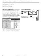
ATC Communicating
Thermostat
CV ECM
Blower
Motor
Diagnostic
Tool
AIRFLOW SELECTION
CFM
HEAT STAGE 1 600
HEAT STAGE 2 750
AUXILIARY HEAT 850
EMERGENCY HEAT 850
COOL STAGE 1 525
COOL STAGE 2 700
COOL DEHUMID 1 425
COOL DEHUMID 2 550
CONTINUOUS FAN 350
HEAT OFF DELAY 60
COOL OFF DELAY 30
PREVIOUS NEXT
Airflow Configuration Screen on Communicating
Thermostat or (ACDU) Service Tool.
DXM2
the cooling mode, it will operate at the lower airflow
to improve latent capacity. The “DEHUM” LED will be
illuminated at all times. Heating airflow is not affected.
Note: Do not select dehumidification mode if cooling
setting is tap 1.
2. Automatic (Humidistat-controlled):
Dehumidification
Mode: When the dehumidification mode is selected (via
DIP switch) AND a humidistat is connected to terminal
DH, the cooling airflow will only be reduced when the
humidistat senses that additional dehumidification is
required. The DH terminal is reverse logic. Therefore, a
humidistat (not dehumidistat) is required. The “DEHUM”
LED will be illuminated only when the humidistat is calling
for dehumidification mode. Heating airflow is not affected.
Summary of Contents for Tranquility TR Series
Page 2: ......


