46
C l i m a t e M a s t e r Wa t e r- S o u rc e H e a t P u m p s
C L I M A T E M A S T E R W A T E R - S O U R C E H E A T P U M P S
Tr a n q u i l i t y
®
3 0 ( T T ) S e r i e s
R e v. : 0 7 / 1 8 / 1 3
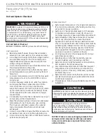
WARNING!
When the disconnect switch is closed, high
voltage is present in some areas of the electrical panel.
Exercise caution when working with energized equipment.
CAUTION!
Verify that ALL water control valves are open and
allow water fl ow prior to engaging the compressor. Freezing
of the coax or water lines can permanently damage the heat
pump.
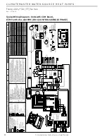
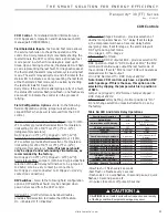
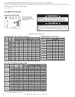
Figure 25: Test Mode Pins
WARNING!
CAUTION!
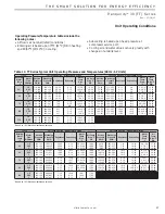
UNIT OPERATING CONDITIONS
LT1
LT2
Short test pins together
to enter Test Mode and
speed-up timing and delays
for 20 minutes.
Unit Start-Up Procedure
ClimaDry
®
II Option Corrections
(When Operating in Non-ClimaDry
®
Mode)
Model
Additional WPD
GPM
PSI
FT
015
1.8
0.32
0.73
2.8
0.77
1.77
018
2.3
0.52
1.20
3.4
1.13
2.62
024
3.0
0.88
2.04
4.5
1.98
4.58
030
3.8
0.62
1.44
5.6
1.35
3.12
036
4.5
0.87
2.02
6.8
1.99
4.60
042
5.3
1.21
2.80
7.9
2.69
6.21
048
6.0
1.55
3.58
9.0
3.49
8.06
060
7.5
1.49
3.45
11.3
3.39
7.82
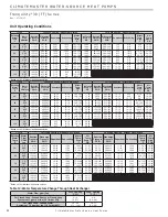
Model
U.S.
GPM
l/s
l/m
Pressure Drop, psi [kPa]*
30ºF [-1ºC]
50ºF [10ºC]
70ºF [21ºC]
90ºF [32ºC]
026
4.0
0.252
15
1.5 [10.3]
1.3 [9.0]
1.1 [7.6]
1.0 [6.9]
6.0
0.378
23
3.1 [21.4]
2.6 [17.9]
2.3 [15.9]
2.1 [14.5]
7.0
0.441
26
4.1 [28.3]
3.4 [23.4]
3.0 [20.7]
2.7 [18.6]
8.0
0.504
30
5.1 [35.2]
4.3 [29.7]
3.8 [26.2]
3.4 [23.4]
038
4.0
0.252
15
1.2 [8.3]
1.0 [6.9]
0.8 [5.5]
0.6 [4.1]
6.0
0.378
23
2.6 [17.9]
2.5 [17.2]
2.3 [15.9]
2.1 [14.5]
8.0
0.504
30
4.5 [31.0]
4.2 [29.0]
4.0 [27.6]
3.7 [25.5]
9.0
0.567
34
5.7 [39.3]
5.2 [35.9]
4.8 [33.1]
4.4 [30.3]
049
5.5
0.347
21
1.1 [7.6]
0.9 [6.2]
0.8 [5.5]
0.7 [4.8]
8.3
0.523
31
2.2 [15.2]
2.1 [14.5]
2.0 [13.8]
1.8 [12.4]
11.0
0.693
42
3.9 [26.9]
3.6 [24.8]
3.2 [22.1]
3.1 [21.4]
12.0
0.756
45
4.5 [31.0]
4.2 [29.0]
3.8 [26.2]
3.5 [24.1]
064
7.0
0.441
26
0.5 [3.4]
0.3 [2.1]
0.2 [1.4]
0.1 [0.7]
10.5
0.662
40
1.9 [13.1]
1.8 [12.4]
1.7 [11.7]
1.6 [11.0]
14.0
0.882
53
3.9 [26.9]
3.5 [24.1]
3.2 [22.1]
2.9 [20.0]
15.0
0.945
57
4.8 [33.1]
4.3 [29.7]
3.9 [26.9]
3.5 [24.1]
072
7.5
0.473
29
1.7 [11.7]
1.5 [10.3]
1.3 [9.0]
1.3 [9.0]
11.3
0.712
43
3.9 [26.9]
3.4 [23.4]
3.0 [20.7]
2.8 [19.3]
15.0
0.945
57
6.9 [47.6]
6.0 [41.4]
5.4 [37.2]
5.0 [34.5]
17.0
1.071
64
8.9 [61.4]
7.7 [53.1]
6.9 [47.6]
6.5 [44.8]
*Note: To convert to kPa millibars, multiply by 10.
Table 10: TT Coax Water Pressure Drop
Motorized Water Valve Option Corrections
Model
Cv
MOPD
WPD Adders (Part Load)
WPD Adders (Full Load)
GPM
PSI
FT
GPM
PSI
FT
026
10.3
150
3.5
0.12
0.27
4.0
0.15
0.35
10.3
150
5.8
0.31
0.72
6.0
0.34
0.78
10.3
150
7.0
0.46
1.07
8.0
0.60
1.39
038
10.3
150
4.0
0.15
0.35
4.5
0.19
0.44
10.3
150
6.0
0.34
0.78
6.8
0.43
0.99
10.3
150
8.0
0.60
1.39
9.0
0.76
1.76
049
10.3
150
5.5
0.29
0.66
6.0
0.34
0.78
10.3
150
8.3
0.64
1.48
9.0
0.76
1.76
10.3
150
11.0
1.14
2.63
12.0
1.36
3.14
064
8.9
150
7.0
0.62
1.43
7.5
0.71
1.64
8.9
150
10.5
1.39
3.22
11.3
1.60
3.69
8.9
150
14.0
2.47
5.72
15.0
2.84
6.56
072
8.9
150
7.5
0.71
1.64
8.5
0.91
2.11
8.9
150
11.3
1.61
3.72
12.8
2.07
4.78
8.9
150
15.0
2.84
6.56
17.0
3.65
8.43

