HRAT E - HRAT/HRAN
12
English 09/02
U N
N4
L2
U3
U1
A1
1 0
12VAC
230VAC
0
14
21 22
12VAC
12VAC
POWER
3
2
C
1
R1
15
16
KM1
18
15
FU2
17
12DC
TK
ID3
ST1
ST2
ST3
ST4
GND
ALL
GND
ALARM
ANALOG INPUT
DIGITAL INPUT
1
E
3
4
2
6
7
8
9
14
15
F3
SA1
SA2
3
F
1
2
4
5
6
10
11
+to
BT1
+to
BT2
+po
BP3
bianco
marrone
RD1
230/24VAC 500mA MAX
1
R2
DIGITAL OUTPUT
D
5
6
YV1
KA2
KM1
1~
M
16
17
E1
KA2
1~
M
A
1
2
3
4
5
6
7
EV1
U1
Z1
U2
Z2
15
KA1
1
2
3
KEYB
26
24
25
A2
5
6
4
24VAC
230VAC
3
TC1
19
20
18
A6
KA1
4
5
5
6
17
33
15
42
42
33
4
0
3
3
0
0
3
3
42
33
0
20
0
19
21
22
30
32
33
35
36
38
39
40
41
42
FU1
FU4
32
42
34
32
33
30
KA1
35
36
17
44
15
37
42
36
42
39
42
40
30
38
42
39
40
38
41
42
27
27
28
28
23
23
24
24
25
26
47
46
45
25
29
45
46
47
15
23
15
24
15
2
17
3
4
5
6
C2
1 0
26
18
15
23
24
15
7
8
3
9
27
28
27
28
ID4
37
34
ID5
34
F5
ID1
F1
F2
ID2
32
33
42
36
44
34
30
39
40
38
41
42
45
46
47
33
15
42
30
42
20
0
MORSETTI PER INSTALLATORE
INSTALLATOR TERMINAL BOX
42
41
FU3
2
2
3
4
0
3
3
0
2
U-V-W-N
PE
230V~50Hz
QF1
U-N
L-N
1
1~
M
2
3
CS
R
KM1
Z1
1
C1
QM1
QS1
UN
45
46
47
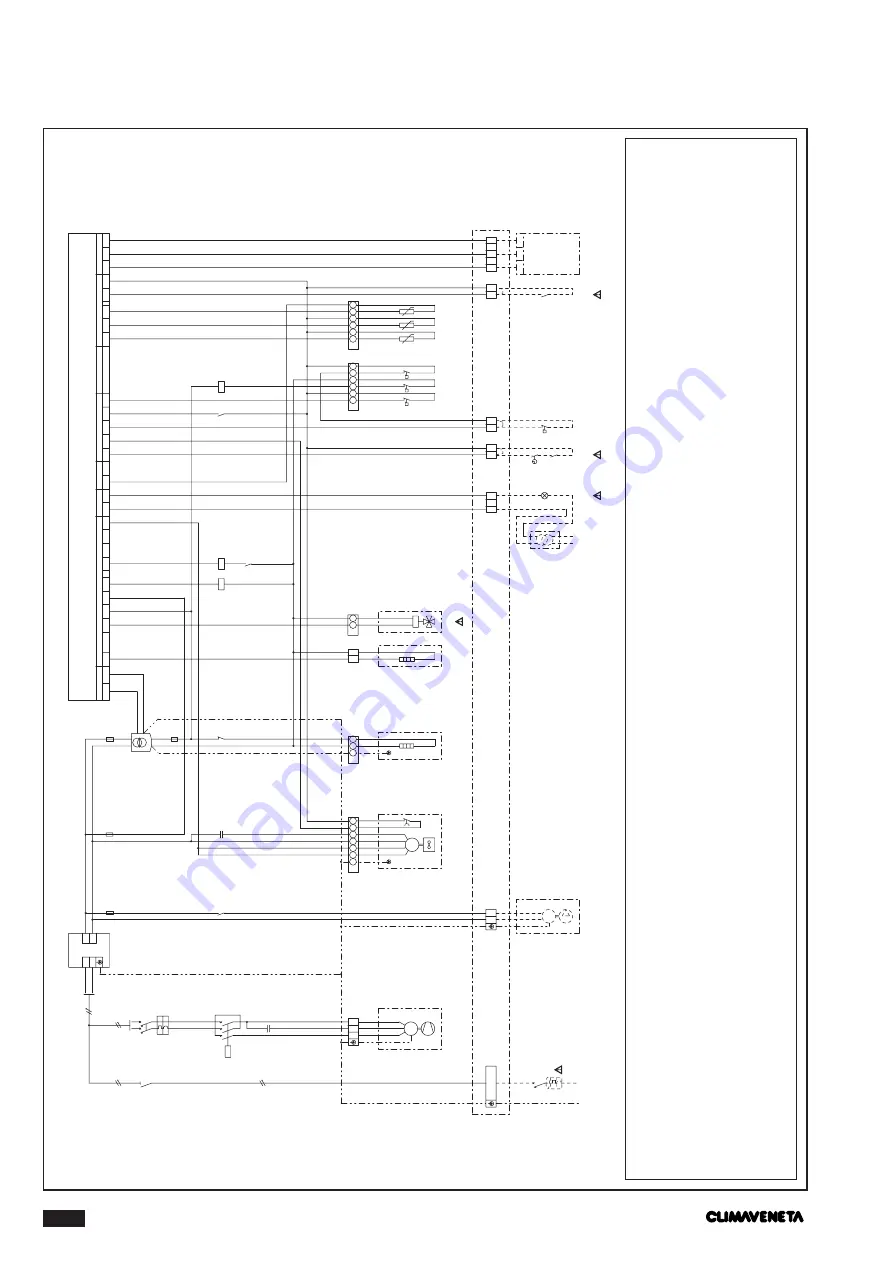
WIRING DIAGRAM 0011-0021 SINGLE PHASE
F
actor
y installed components
A1
Radio interf
er
ence suppr
esser
A2
Electr
onic contr
oller
A6
Unit contr
ol displa
y k
eyboar
d
BP3
Condensing/e
va
poration contr
ol pr
essur
e transducer
BT1
Installation water inlet temperatur
e sensor
BT2
Installation water outlet temperatur
e sensor
C1
Compr
essor star
t ca
pacitor
C2-3
Fan star
t ca
pacitor
E1
W
ater pump
EV1-2
Fans
F1
High pr
essur
e s
w
itch
F2
Lo
w pr
essur
e s
w
itch
F3
Flo
w s
w
itch
F5
W
ater diff
er
ential pr
essur
e s
witch
FU1
Transf
ormer pr
otection fuse
FU2
Auxiliar
y cir
cuit fuse
FU3
Fan pr
otection fuse
FU4
W
ater pump pr
otection fuse
KA1
High pr
essur
e s
w
itch r
ela
y
KA2
W
ater pump contr
ol r
ela
y
KM1
Compr
essor contactor
QF1
Chilling assembl
y pr
otection s
witch
QM1
Compr
essor thermal o
verload s
w
itch
QS1
Door lock disconnector s
witch
R1
Compr
essor oil sump heater
R2
Fr
ost heater
RD1
Red lock
out warning light
SA1
On-off s
witch and/or timer input
SA2
Summer
-winter s
w
itch input
TC1
Saf
ety transf
ormer
YV1
Cycle r
ev
ersal valv
e
Z1
Compr
essor
1
Switch not included in the suppl
y
3
Heat pumps onl
y
4L
ights not supplied
5
Optional on-off s
witch and timer
6
Optional summer
-winter s
w
itch;
for cooling-onl
y mod-
els terminals 8-9 closed


