HRAT E - HRAT/HRAN
25
English 09/02
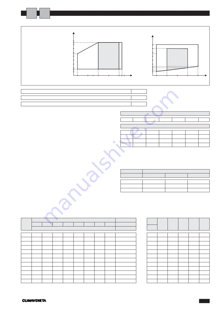
OPERATING LIMITS
Meters
1
5
10
15
20
Model
cPf
cQ
cdp
0
1
1
1
12%
0,985
1,02
1,07
20%
0,98
1,04
1,11
28%
0,974
1,075
1,18
35%
0,97
1,11
1,22
40%
0,965
1,14
1,24
Water thermal head min-max
3÷8
Hydraulic circuit pressure min-max (bars)
1÷3
Max. storage temperature (°C)
63
ETHYLENE GLYCOL SOLUTIONS
Water and ethylene glycol solutions used as a thermal
vector in the place of water reduce the performance
of the unit. Multiply the performance figures by the
values given in the following table.
0
-5
-10
-15
-20
-25
Freezing point (°C)
Percentage of ethylene glycol by weight
cPf: correction factor cooling capacity
cQ: correction factor flow rate
cdp: correction factor pressure drop
f1
correction factor capacity
fk1
correction factor compressor power input
fx1
correction factor total power input
FOULING FACTORS
The performance data given refer to conditions with
clean evaporator plates (fouling factor=1).
For different fouling factors, multiply the figures in the
performance tables by the coefficient given in the fol-
lowing table.
0011
50
41
35
32
29
0021
55
46
40
37
34
0025
55
46
40
37
34
0031
55
46
40
37
34
0041
58
49
43
40
37
0051
58
49
43
40
37
0061
58
49
43
40
37
0071
65
56
50
47
44
0091
65
56
50
47
44
0101
65
57
52
49
46
0121
65
57
52
49
46
0151
65
57
52
49
46
Octave band (Hz)
Gr.
63
125
250
500
1000
2000
4000
8000
Total dB(A)
Sound pressure level (dB)
0011
58
48
47
46
43
39
33
35
50
0021
65
55
54
53
50
46
40
42
55
0025
65
55
54
53
50
46
40
42
55
0031
63
53
52
51
48
44
38
40
55
0041
68
58
57
56
53
49
43
45
58
0051
68
58
57
56
53
49
43
45
58
0061
68
58
57
56
53
49
43
45
58
0071
75
65
64
63
60
56
50
52
65
0091
75
75
64
63
60
56
50
52
65
0101
75
75
64
63
60
56
50
52
65
0121
75
75
64
63
60
56
50
52
65
0151
75
75
64
63
60
56
50
52
65
A
I
4,4 x 10
-5
0,86 x 10
-4
1,72 x10
-4
-
0,96
0,93
-
0,99
0,98
-
0,99
0,98
Fouling factors
(m
2
°C/W)
f1
Evaporator
fk1
fx1
SOUND PRESSURE LEVEL
Reference point: at 1 m from the surface of the unit on the coil side and 1 m above the support surface.
5
10
15
20
25
30
8
28
35
40
45
43
-25
-15
-10
20
5
-5
15 18
t
°
t
°
-10
-5
-3
-7
5
0
10
15
20
25
30
35
45
40
50
t
°
t
°
To operate the
chiller, it is vital to
respect the condi-
tions given in the
table:
for model 0151 max
external air tempera-
ture = 40°C.
COOLING
ZONA
DI LAVORO
CONSIGLIATA
ZONA
DI LAVORO
CONSIGLIATA
HEATING
WATER OUTLET TEMPERATURE
WATER OUTLET TEMPERATURE
EXTERNAL AIR
TEMPERA
TURE
EXTERNAL AIR
TEMPERA
TURE


