background image

16

EN

ELECTRONIC CONTROL

Follow the instructions shown in the HRD2 CR Control Manual supplied with the unit.

ROUTINE AND UNSCHEDULED MAINTENANCE

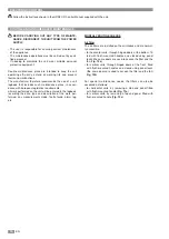
BEFORE CARRYING OUT ANY TYPE OF MAINTE-
NANCE, DISCONNECT THE UNIT FROM THE POWER
SUPPLY.

• The user is responsible for ensuring correct maintenance

of the appliance.

• The maintenance operations must be carried out by quali-

fied personnel.

• If needing to dismantle the unit, wear suitable personal

protective equipment.

Routine maintenance plans are intended to keep the unit
operating efficiently, extend its working life and prevent
faults and malfunctions.
The manufacturer therefore recommends the use of a unit
logbook that includes such maintenance plans, in accor-
dance with European legislative requirements; 
all work performed on the unit will be entered in the logbook,
recording the date, type and description of the work per-
formed, any measurements made, faults found, alarm log,
etc.

MONTHLY ROUTINE CHECKS

Air filter

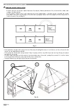
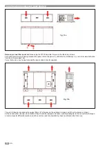
The air filters are installed on the air intakes and are normal-
ly accessible:
• for horizontal units, through hinged doors at the bottom, fit-

ted with flush-mounted handles and closed using panel
locks (the same doors are used to access the filter and the
fan; 

Fig. 12a

)

• for vertical units, through hinged doors at the front, fitted

with flush-mounted handles and closed using panel locks
(the same doors are used to access the filter and the fan;

Fig. 12b

)

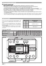
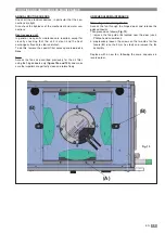
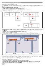
For special maintenance needs, the filters can also be
accessed as follows:
• for horizontal units, by removing a side end panel fitted

with flush-mounted handle 

(Fig. 13a

)

• for vertical units, by removing a top end panel fitted with

flush-mounted handle (

Fig. 13a

)

Summary of Contents for HRD2 050

Page 1: ...TA EFFICIENZA EN HIGH EFFICIENCY VENTILATION UNIT WITH HEAT RECOVERY IT Vi preghiamo di leggere con attenzione il presente manuale prima di mettere in funzione l apparecchio EN Please carefully read t...

Page 2: ...e e danneggiare irreparabilmente le loro componenti e loro strutture Tali ambienti devono essere caratterizzati da temperatu ra dell aria non inferiore a 20 C e non superiore a 45 C e da umidit relati...

Page 3: ...onsabilit per danni a persone o cose derivati dalla mancata consultazione delle prescrizioni contenute in questo manuale Uso proprio ricambio meccanico dell aria con recupero di calore negli ambienti...

Page 4: ...o a sinistra rispetto al pannello quadro elettrico Modulo batteria acqua raffreddamento riscaldamento Modello 050 090 140 210 300 410 L mm 1350 1470 1850 1850 2150 2150 W mm 680 820 1030 1460 1460 184...

Page 5: ...ia di rinnovo inferiore a sinistra rispetto al pannello quadro elettrico HRD2 Modulo batteria acqua raffreddamento riscaldamento Modello 050 090 140 210 300 410 L mm 1350 1470 1850 1850 2150 2150 W mm...

Page 6: ...ensili sopra l unit imballata Prima di posizionare l unit considerare le dimensioni fuori tutto e gli spazi tecnici di rispetto caratteristici per permettere agevolmente le connessioni elettriche aera...

Page 7: ...riportate in questo manuale Le componenti impiegate come ricambio devono essere originali e o corrispondere alle specifiche del Costruttore N B L installatore tenuto a considerare altri tipi di risch...

Page 8: ...ico del l acqua condensata dare una pendenza 3 min alla mac china verso il punto di scarico della stessa Lasciare opportuni spazi tecnici di rispetto come indicato nelle figure 5 e 6 seguenti Essi son...

Page 9: ...o even tualmente registrare il fissaggio su tiranti opportuni fino a che i pannelli laterali amovibili si possano smontare e rimontare senza impedimento Per l unit in versione verticale ancorare gli z...

Page 10: ...secondo le istruzioni successive va scambiato con l elemento di tettuccio dell unit collo cato sull estremit di accoppiamento fig 9 Per il montaggio degli elementi di tetto svitare preventivamente la...

Page 11: ...razione va condotta prima di installare l unit Applicare preventivamente sul modulo la guarnizione fornita in kit sul lato di connessione alla macchina fig 10 Per moduli in versione orizzontale impieg...

Page 12: ...mfort acustico richiesto dall ambiente da essa asservito Interporre tra le prese d aria della macchina e le condotte dell aria opportune giunzioni antivibranti garantire comunque la continuit elettric...

Page 13: ...a Il percorso dei tubi deve essere tale da non interferire con la eventuale rimozione del modulo Seguire le istruzioni di INGRESSO ACQUA etichetta IN ed USCITA ACQUA etichetta OUT per la connessione d...

Page 14: ...di alimenta zione elettrica od al dispositivo di protezione elettrica Collegare l unit ad una opportuna presa di corrente sfruttando i pressacavi in prossimit del quadro elettrico ed impie gando i ter...

Page 15: ...15 IT HRD2 090 140 210 HRD2 300 410...

Page 16: ...intrapresi sull unit annotando data tipo e descrizione dell intervento rilievi strumentali anomalie rilevate cronologia degli allarmi ecc CONTROLLO ORDINARIO MENSILE Filtri aria I filtri aria sono dis...

Page 17: ...nti filtranti impedito da una lamina bloccafiltro che va ruotata di 90 dotarsi di cacciavite con testa a croce dopo aver rimontato gli elementi filtranti ruotare la lamina in senso contrari fino al co...

Page 18: ...la barra verticale di sostegno Per l unit in versione verticale una volta sbloccato traslare direttamente il pannello verso l alto L unit equipaggiata standard di filtri compatti ad efficienza F7 sull...

Page 19: ...Accedere ai ventilatori come precedentemente descritto per i filtri aria impiegando esclusivamente gli sportelli incernierati figure 12a e 12b e verificare la perfetta pulizia e la libera rotazione d...

Page 20: ...vano accessibile del l attuatore Quindi fig 16a e 16b 1 allentare il dado di fissaggio C del perno della serranda usare chiave esagonale da 8mm 2 sganciare l attuatore dal suo fermo in plastica D 3 so...

Page 21: ...ag giungere entrambi i pulsanti In caso di sostituzione dell elemento riscaldante procedere come segue 1 rimuovere anche il pannello centrale 2 scollegare il connettore rapido del riscaldatore 3 con c...

Page 22: ...Collegamenti elettrici sbagliati o allentati Protezione termica attiva Assenza segnale regolazione Alimentare l unit Ripristinare le corrette connessioni elettriche Controllare l assorbimento elettri...

Page 23: ...USER AND INSTALLATION MANUAL EN HIGH EFFICIENCY VENTILATION UNIT WITH HEAT RECOVERY EN Please carefully read this manual before operating the appliance MODELS HRD2 050 410 Air flow rate 450 3800 m3 h...

Page 24: ...poten tially explosive which may attack and irreparably dam age their components and structures The installation air temperature must not be lower than 20 C or higher than 45 C and relative humidity...

Page 25: ...things resulting from the failure to heed the instructions contained in this manual Intended use mechanical air change with heat recovery in the environmental and operating conditions speci fied previ...

Page 26: ...left with reference to the electrical panel Model 050 090 140 210 300 410 L mm 1350 1470 1850 1850 2150 2150 W mm 680 820 1030 1460 1460 1840 H mm 330 370 455 455 590 590 W1 mm 760 900 1110 1540 1540...

Page 27: ...supply from bottom left with reference to the electrical panel HRD2 Water coil module cooling heating Model 050 090 140 210 300 410 L mm 1350 1470 1850 1850 2150 2150 W mm 330 370 455 455 590 590 H m...

Page 28: ...ion site or place of storage no objects or tools are stacked on top of the packaged unit Before positioning the unit take into account the overall dimensions and required clearances so as to simplify...

Page 29: ...his manual The components used as spare parts must be original and or correspond to the manufacturer s specifications N B The installer must take into account other types of risk during assembly for e...

Page 30: ...drainage of the condensate tilt the unit slightly min 3 towards the drainage point Leave suitable clearance as shown in Figures 5 and 6 below This clearance is needed to allow the unit to be accessed...

Page 31: ...the anchoring using suitable tensioners so that the removable side panels can be removed and replaced without obstructions For the vertical version anchor the base mouldings to the floor placing a vib...

Page 32: ...he instructions in paragraph below needs be swapped with the canopy element fixed on the end of the unit Fig 9 To assemble the canopies first unscrew the set of M6 screws A in Fig 9a using a 4 mm Alle...

Page 33: ...he self tapping screw kit supplied Fig 8 This operation needs to be completed before installing the unit First apply the gasket supplied in the kit to the unit connection side of the module Fig 10 For...

Page 34: ...uired in the air conditioned environment Install suitable vibration isolating joints between the air openings on the unit and the air ducts always ensure electrical continuity between the unit and the...

Page 35: ...stressing the coil manifolds The layout of the pipes must be such as to not obstruct removal of the module Observe the WATER INLET labelled IN and WATER OUTLET labelled OUT markings when connecting th...

Page 36: ...tion device Connect the unit to a suitable power outlet running the cable through the cable glands near the electrical panel and using the screw terminals for connection to the controller and spring t...

Page 37: ...15 EN TEMPERATURE PROBES L3000mm CABLE M1 CABLE M2 CABLE MBP HRD2 090 140 210 TEMPERATURE PROBES L3000mm CABLE M1 CABLE M2 CABLE MBP HRD2 300 410...

Page 38: ...slative requirements all work performed on the unit will be entered in the logbook recording the date type and description of the work per formed any measurements made faults found alarm log etc MONTH...

Page 39: ...lters can be slid out by rotating the filter locking plate by 90 use a Phillips head screwdriv er after having repositioned the filters turn the plate in the opposite direction until it touches the fi...

Page 40: ...e vertical support bar For vertical units once having released the panel slide it directly upwards The unit is fitted as standard with compact filters F7 efficiency on the outside air intake and M5 on...

Page 41: ...r access panels one at a time Fans Access the fans as described previously for the air filter using the hinged doors only figure 12a and 12b and make sure the impellers are perfectly clean and rotate...

Page 42: ...Fig 16a and 16b 1 loosen the fastening nut C on the damper shaft use an 8 mm Allen key 2 release the actuator from its plastic catch D 3 lift the actuator until it comes loose from the shaft and slide...

Page 43: ...s to the filters Fig 17 if necessary use a screwdriver to reach the buttons If needing to replace a heating element proceed as follows 1 also remove the middle panel 2 unplug the quick connector on th...

Page 44: ...r supply Incorrect or loose electrical connections Thermal protector activated No control signal Power on the unit Restore correct electrical connections Check power consumption Check signal connectio...

Page 45: ......
Page 46: ...es France www climaveneta fr Spain www climaveneta es Poland www climaveneta pl Germany www climaveneta de Great Britain www climaveneta co uk Russia ru climaveneta com China www climaveneta com cn In...

Reviews: