background image


2


Power Supply 

A Power Adapter is required to connect to a wall power outlet. Be sure only to use an adapter with 
the appropriate AC voltage rating to prevent component damage. A DC 12V 1A output Power 
Adapter is generally used to power the Repeater. 

Power Adapter Application: 

To connect the Power Adapter: 

Step 1


Locate the Power Adapter and plug into the DC power jack. 

Step 2


Plug the Power Adapter to a wall power outlet. 

Step 3


The Repeater will sound a Long beep and the Green LED will light up. 

AC Failure/AC Restore: 

The Repeater will send an AC Failure signal to the Control Panel when the Power Adapter is 
unplugged for 30-60 seconds. When the Power Adapter is plugged in again for 30-60 seconds, the 
Repeater will send an AC Restore signal to the Control Panel. 

Rechargeable Battery: 

In addition to the adapter, there is a rechargeable battery inside the Repeater, which serves as a 
back-up power in case of a power failure. 

When the Power Adapter is plugged into the DC power jack, slide the Battery Switch to the ON 
position so the Power Adapter supplies power to the Repeater and at the same time recharges the 
battery. It takes approximately 72 hours to fully charge the battery. 

When the Power Adapter is unplugged, the Repeater will be powered by the rechargeable battery. 

The Repeater can detect the battery voltage. When the battery voltage is low, the Green LED will 
flash to indicate low battery status. 


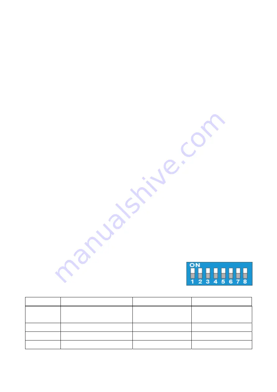
Functional Switch Block 

The Functional Switch Block determines which Mode the Repeater is 
in. A switch in the up position indicates the (

ON

) Mode. Likewise, a 

switch in the down position indicates the (

OFF

) Mode. 


Function 

ON 

OFF 

DIP Switch 1  Learn Device 

Learning mode 
(Device) 

Normal Mode 

DIP Switch 2  Range or Walk Test 

Walk Test Mode 

Normal Mode 

DIP Switch 3  Factory Reset 

Clear Mode 

Normal Mode 

DIP Switch 4  Learn into Control Panel 

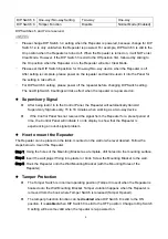
Learning mode (Panel)  Normal Mode 

Summary of Contents for RP-29

Page 1: ...attery low on power 2 Mode LED Yellow On The Repeater is in Learning Mode Panel or Clear Mode Flash 1 flash every second The Repeater is in Walk Test Mode Slow Flash 1 flash every 2 seconds The Repeat...

Page 2: ...ble battery inside the Repeater which serves as a back up power in case of a power failure When the Power Adapter is plugged into the DC power jack slide the Battery Switch to the ON position so the P...

Page 3: ...r will automatically transmit Supervisory Signals every 15 to 18 minutes when working as a two way device If the Control Panel has not received the signal from the Repeater for a preset period of time...

Page 4: ...ual Step 3 Press the Test button The Repeater will transmit a Test Code to the Control Panel as the Red LED lights up and the Repeater emits 1 beep Step 4 If the Repeater receives an acknowledge signa...

Page 5: ...n code from the devices For PIR Camera please press the test button once to send a learn code to the Repeater If the Repeater receives a learn code from a new device it will emit 1 long beep and the B...

Page 6: ...3 To exit Clear Mode slide DIP Switch 3 to the Off position The Repeater will emit 1 long beep and the Yellow LED will turn off NOTE Whenever the Repeater is removed from the Control Panel it should...

Page 7: ...ended to link not more than two layers of repeaters From the example below Device to B to A to Control Panel Repeater A Repeater B and the Device all need to be learned into the Control Panel The Devi...

Page 8: ...to learn the device into Repeater A only learn into Repeater B only learn into Repeater C only or learn into Repeaters A B and C It is recommended to learn the device into Repeater A only or Repeater...

Page 9: ...is connected Consult the dealer or an experienced radio TV technician for help FCC Caution To assure continued compliance any changes or modifications not expressly approved by the party responsible...

Reviews: