background image


46 


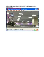
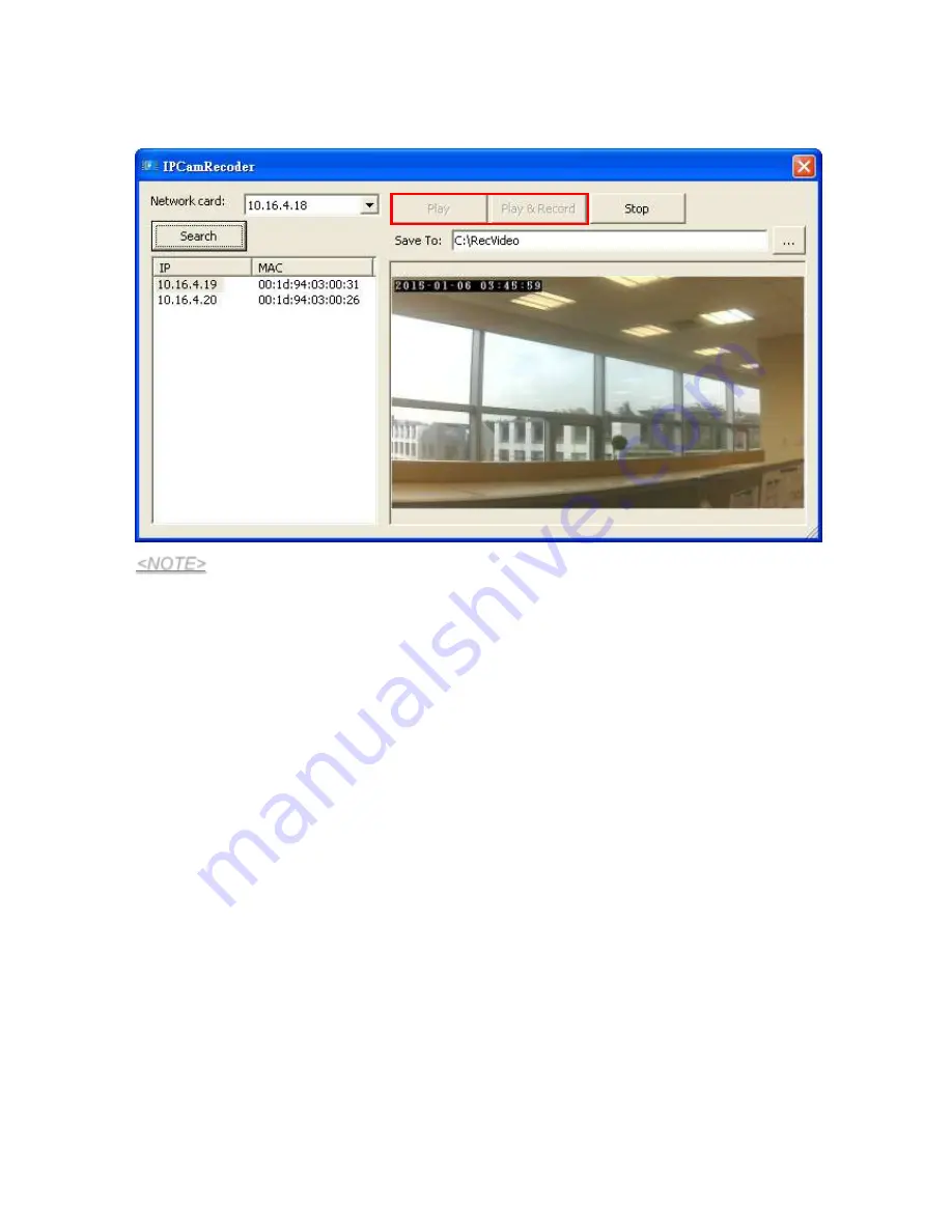
When playing and/or recording, the 

Play

” and “

Play & Record

” button will dim and are 

thus unable to be selected. Press 

Stop

” anytime to stop viewing and/or recording. 


<NOTE> 

  The videos are directly stored into the designated location. It is advised that the 

videos  should  be  checked  and  managed  routinely  to  prevent  overloading  the 
storage space. 


Summary of Contents for VST-1818

Page 1: ...September 30 2017 ...

Page 2: ...TIME STAMP __________________________________________________________________ 23 5 4 STREAM SETTING ______________________________________________________________ 24 5 5 RECORDED FILES ______________________________________________________________ 25 5 6 ALARM SETTING _______________________________________________________________ 26 6 NETWORK SETTING ______________________________________________...

Page 3: ...A __________________________________________________ 47 10 1 HOME PORTAL SERVER__________________________________________________________ 47 10 2 PORT FORWARDING_____________________________________________________________ 48 11 CONNECTING TO CLIMAX CONTROL PANELS___________________________________________ 53 11 1 LEARNING THE IP CAMERA INTO THE CONTROL PANELS __________________________________ 53...

Page 4: ... VST 1818LR WI Indoor Internal Antenna Yes No VST 1818SLIM Indoor No No No 1 1 Function Overview The VST 1818 IP Camera includes a variety of functions that can be adjusted to suit different necessities Below is an overview of the functions of the IP Camera Alarm triggered video recording that includes Pre alarm recording to see how alarm was triggered Please see 5 IP Camera 5 6 Alarm Setting 24 h...

Page 5: ... Enter exit privacy mode On The IP Camera is in privacy mode 6 Internet Connection LED Blue On connected to internet wired or wireless Off disconnected from internet Flashes for 5 minutes The IP Camera is in learning mode Flashes quickly The IP Camera is streaming or recording 7 Speaker 8 WPS Button 9 Privacy Button Press and hold for 2 seconds until warning LED flashes twice let go to enter or ex...

Page 6: ...s and hold for 10 seconds to enter learning code Press and hold for 6 seconds to exit learning mode 3 Microphone 4 Power LED Green On powered Off unpowered 5 Warning LED Red Flashes for 2 3 seconds Activating WPS protocol Flashes 3 times WPS pairing successful Flashes twice Enter or exit privacy mode On The IP Camera is in privacy mode 6 Internet Connection LED Blue On connected to internet wired ...

Page 7: ...er adapter is required to connect to a wall outlet Be sure only to use an adapter with the appropriate AC voltage rating to prevent component damage A 5V DC output and 1A adapter is generally used to power the IP Camera 2 4 System Requirements The system requires a TCP IP network environment To install the CD Wizard your computer must have Microsoft Windows 98 ME NT4 0 2000 XP Vista 7 or 8 operati...

Page 8: ...er and Ethernet cables With Wired Connection Step 2 Find a suitable location to mount the IP Camera Step 3 Plug in the enclosed Ethernet cable NOTE If the IP Camera is to complement with a Control Panel connect the IP Camera and the Control Panel to the same router to learn the IP Camera into the Control Panel Please refer to 11 Connecting to the Climax Control Panels if you wish to increase the f...

Page 9: ...etween the base and the head The Head connects the IP Camera to the whole camera stand Below outlines the steps to mount the IP Camera to a surface Step 1 Find a surface to mount the camera stand Locate the 2 mounting holes of the Base and use them as template mark the surface Step 2 Apply wall plugs if fixing onto plaster or brick Screw the Base onto the surface ...

Page 10: ...8 Step 3 Attach the Head to the Shaft by rotating the Head clockwise onto the Shaft Step 4 Attach the Shaft onto the Base by rotating the Shaft clockwise onto the Base ...

Page 11: ...9 Step 5 Turn the Camera Angle Knob clockwise as shown below to tighten the Camera Mount Screw to the Cap ...

Page 12: ...10 Step 6 Tighten the Camera Locking Collar rotating it clockwise as shown below Step 7 Turn the Camera Angle Knob counter clockwise as shown below to loosen the Camera Mount Screw from the Cap ...

Page 13: ...to the Camera Stand Mounting Hole of the IP Camera by turning the Camera Locking Collar counter clockwise as shown below Step 9 Find a desired angle for the IP Camera and turn the Camera Angle Knob clockwise to stabilize the Camera Mount Screw ...

Page 14: ...entify the IP Camera on the LAN To install the Finder software Step 1 Insert the supplied CD ROM into your CD ROM drive Step 2 Find the Finder software in the CD ROM Step 3 Double click on the Finder_v1 x to initiate the installation Step 4 Follow on screen instruction to complete installation Step 5 Once complete the Finder icon will be displayed on your desktop Step 6 Double click on the Finder ...

Page 15: ... displayed check camera power and Ethernet connection and click on Search to update the panel information Step 8 Optional You can choose to edit the camera s network setting manually by clicking on the panel column then click Configure Setting ...

Page 16: ...nter the user name default admin and password default admin1234 then click OK to confirm The user name and password can be changed later in the camera s configuration webpage Step 9 Click the camera information column and click on Open Web Page or double click on the camera column to link to the panel configuration webpage Your default browser will start automatically to connect to the LAN IP disp...

Page 17: ...back to its original settings Step 1 Disconnect the AC power by unplugging the 5V DC power adapter Step 2 Press and hold the Privacy Button and plug in the 5V DC power adapter Step 3 Continue holding the Privacy Button for roughly 30 seconds time ...

Page 18: ... Disconnect the AC power by unplugging the 5V DC power adapter Step 2 Press and hold the Privacy Button and plug in the 5V DC power adapter Step 3 Continue holding the Privacy Button for roughly 30 seconds time Step 4 When all 3 LEDs flash 3 times simultaneously followed by complete dimming of all LEDs let go of the Privacy Button Step 5 The IP Camera has reset please wait for it to start up ...

Page 19: ...nter the User name Password to proceed Default user name admin Default password cX HsA 7F1 If wrong user name and password are entered for 5 times the local webpage login will be disabled for 5 minutes Step 3 You will enter change password page Enter and repeat a new password username change is optional take care that both username and password are case sensitive Click OK to confirm Step 4 Upon co...

Page 20: ...ns on the left sided panel and the IP Camera will prompt you to re login with new username and password Please use this new set username and password for future log in Please refer to 7 System Setting 7 1 Change Password for more details ...

Page 21: ...s configuration webpages for you to manage your IP Camera and view videos 5 1 Image Tuning Click on Image Tuning to adjust video preferences according to the below parameters 5 2 Motion Detection Motion Detection includes motion detection related setting options ...

Page 22: ... Region 1 is ticked and it detection coverage includes the whole camera view If Motion Detection Enable is ticked but neither of Region 1 or Region 2 is ticked The IP Camera will not be able to detect any movement Please click the OK button for the changes to be effective Motion Detection Region You can choose the location size and sensitivity of the motion detection region by adjusting the parame...

Page 23: ...xels of Left determines the horizontal starting position of the region for detection The value 100 pixels of Top determines the vertical starting position of the region for detection As shown a value of 100 pixels are entered for both Width and Height therefore a 100 by 100 motion detection region is determined ...

Page 24: ...tion detection according to the set parameter You can refer to the horizontal and the vertical scales provided on the respective bottom and right side of the live feed When confirmed press OK to submit your adjusted parameter Press Reset to re enter the parameters Reset button resets the parameters to the previously set parameters ...

Page 25: ...for you to edit the Time Stamp format on the video Position The available options are Date Format The available options are Time Format The available options are Press OK to submit your adjusted parameters Press Reset to re select the parameters ...

Page 26: ...ustable Increasing FPS improves the quality of the live stream Click OK to confirm changes or click Reset to reset to the previously set parameters Port The port number for obtaining HD 1280x720 resolution H264 video stream The factory default is set to 0 and H264 streaming is disabled To enable H264 streaming please set a port number Motion JPEG Stream Quality adjusts the quality of the stream MJ...

Page 27: ...s powered down Switching memory types require a restart of the IP Camera The IP Cam supports Micro SD Card with up to 32GB storage capacity Click on the buttons for the respective functions described below All to select all the recorded videos None to cancel selecting the recorded videos Half Old to select the older half the recorded videos Invert to invert the current selection E g if All was sel...

Page 28: ...h of the video which will be recorded prior to the initiation of video recording Default 10 seconds EXAMPLE When Total Time is set to 30 seconds and Pre Alarm Time is set to 10 seconds the IP Camera will keep a continuous last 10 second buffer video storage When the IP Camera receives command to record a video motion detection alarm trigger from panel request from panel the IP Camera will record a...

Page 29: ...eft in the MicroSD card or RAM the IP camera will start deleting old videos to retain more space Press OK to submit the updated programmed parameters Or press Reset to re enter Reset button resets the parameters to the previously set parameters An error message will appear on top of the page if the parameters are not logically set e g Pre alarm Time 20 seconds Total Time 10 seconds as exemplified ...

Page 30: ...efault DNS 1 and Default DNS 2 Please make sure that you have obtained all required values according to your Network environment Please contact your network administrator and or internet service provider for more information DNS Flush Period You can set the system to clear current DNS resolution records for all entered URL settings Reporting Upload XMPP etc after a set time period The system will ...

Page 31: ...Fi AP Click Scan WiFi AP to search for available wireless network Select the available Wireless APs from the list by clicking Set after AP info column and enter the required information pre shared key etc and click the OK button 2 Enter the Wireless information manually and click OK to connect 3 WPS protocol Use the WPS protocol to connect it to the Wi Fi network ...

Page 32: ...t pairing When WPS pairing is successful the Red LED of IP Camera will flash 3 times NOTE After wireless information are successfully entered or when WPS pairing has succeeded please reboot the system and ONLY choose one type of connection either wired or wireless at a time For wireless connection please remove the network cable and the power cable Reconnect the power cable only and wait for it to...

Page 33: ...rol and data transfer among networked devices at home office or public spaces You can configure this setting to allow for Port Forwarding connection to the IP camera Enable UPnP Device When enabled you will be able to see this device via any UPnP discovery tool Enable UPnP Port Redirect The device will try to find an UPnP supported router and set up the port to redirect to the router Port Forwardi...

Page 34: ...m Setting 7 1 Change Password Edit the username and password used to log into IP Camera webpage under Change Password page Enter a new name or new password and click OK to confirm the username and password change ...

Page 35: ...33 7 2 Report The Report Function is Read Only and is currently unavailable for setting please skip this part ...

Page 36: ...pload to server http server path or https server path After registering the IP Camera in Home Portal Server the first 2 URLs of Media Upload setting will be programmed automatically according to Home Portal Server setting Please do not manually modify this setting Any modifications may cause problems when operating on the Home Portal Server or when connecting to the Control Panel ...

Page 37: ...35 7 4 XMPP The XMPP page allows you to connect to the Home Portal Server for remote control Please do not modify any settings or the IP Camera may lose connection with Home Portal Server ...

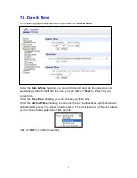
Page 38: ...f with the time you can click on Now to refresh to your current time Under the Time Zone heading you can choose your time zone Under the Internet Time heading you can tick the box Automatically synchronize with an Internet time server to adjust to internet time The scroll down bar of Server allows you to choose from a selection of time servers Click on OK to confirm the settings ...

Page 39: ...provides IP Camera public IP information Dynamic DNS Server Set the server used by IP Camera to acquire its public IP address Public IP address The public IP address shown is required to for remote access of the IP Camera via port forwarding ...

Page 40: ...update the firmware of the IP Camera Click the Choose File button browse and find the correct file and press Apply to apply the setting Please follow the onscreen instruction to complete the update It is also recommended to select Do factory reset recommended when upgrading a firmware ...

Page 41: ...era setting event records and restore all settings to factory default You can choose to reset the IP camera to the factory default setting by clicking the Yes button If you wish to keep the current network setting you can tick the Keep current network setting option ...

Page 42: ...ed when you click on Backup Restore You can store the current settings by clicking on the Download button If you wish to restore the previously stored file click on Choose File find the correct file and click on Apply to restore to the previous setting ...

Page 43: ...Log displays system operation history You can choose how many reported events are displayed by selecting the drop down bar near the bottom of the page or click Download button to download detailed system log file into your computer ...

Page 44: ... camera 7 12 Reboot The Reboot function allows you to restart the IP Camera By pressing the Reboot button a box will display Press the OK button the Camera will automatically start rebooting process and counts the time with Elapsed time XX seconds when progressing The amount of Elapsed time depends on system itself once successful restarting system will go back and display the main webpage ...

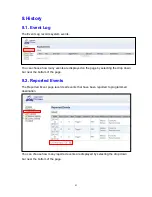
Page 45: ...played on the page by selecting the drop down bar near the bottom of the page 8 2 Reported Events The Reported Event page records all events that have been reported to programmed destination You can choose how many reported events are displayed by selecting the drop down bar near the bottom of the page ...

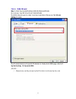
Page 46: ... and operation The Network Video Recorder software are included in VST 1818 installation CD as shown Please execute the VLClib file first then the IPCamRecoder file After installation execute the IPCamRecoder software Below is a display of the IPCamRecoder window Step 1 With the Search button you can find the IP Camera on the local area network LAN much like the Finder application Step 2 Choose on...

Page 47: ... Stop Play View the High Definition live feed on the IP Camera Play Record View and Record the live feed on the IP Camera You can record videos continuously Each video is divided into 1 hour duration unless you press Stop before the 1 hour period expires Stop Press this button to stop viewing and or recording the high definition live feed ...

Page 48: ...ll dim and are thus unable to be selected Press Stop anytime to stop viewing and or recording NOTE The videos are directly stored into the designated location It is advised that the videos should be checked and managed routinely to prevent overloading the storage space ...

Page 49: ...Forwarding function 10 1 Home Portal Server The Home Portal Server is a server established by Climax You can learn the IP Camera into a Climax Home Security Control Panel then register the panel in Home Portal Server to view IP Camera streaming video as part of the Home Portal Server function Please refer to the Home Portal Server User Guide in your Control Panel s Installation CD for more informa...

Page 50: ...remote site 10 2 1 Application needed You will need to have a media player that supports RTSP For the example below we will be using the VLC media player as it is free and supports RTSP 10 2 2 Open Network Stream Step 1 On VLC media player select Media and select Open Network Stream as shown in the following ...

Page 51: ...a MJPG streaming port is set to 80 by default and cannot be changed The IP entered above is the public IP obtained on the Dynamic DNS page refer to 7 System Setting 7 6 Dynamic DNS You may adjust the video streaming quality in IP Camera Setting Refer to Port 2 of 5 IP Camera 5 4 Stream Setting NOTE Please make sure the port used by the IP Camera is not blocked by the router ...

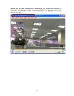
Page 52: ...50 Step 2 Click on Play to access the IP Camera the VLC media player will begin to stream the video from the camera the streaming URL will be displayed on top of the VLC media player ...

Page 53: ...30 221 59003 IPCAM The H264 streaming port number must be programmed Please see 5 4 Stream Setting for detail The IP entered above is the public IP obtained on the Dynamic DNS page refer to 7 System Setting 7 6 Dynamic DNS NOTE Please make sure the port used by the IP Camera is not blocked by the router ...

Page 54: ...52 Step 2 Click on Play to access the IP Camera the VLC media player will begin to stream the video from the camera the streaming URL will be displayed on top of the VLC media player ...

Page 55: ...W Control Panel Step 2 Assuming HPGW is properly installed open its webpage Step 3 Put the Control Panel into learning mode according to manual instruction Step 5 Press and hold the Privacy Button on the IP Camera for 10 seconds to enter learning mode The Blue LED will start to flash Step 6 If the Control Panel detects the IP Camera please refer to the Control Panel manual on how to complete learn...

Page 56: ...nel into learning mode according to manual instruction Step 5 Press and hold the Privacy Button on the IP Camera for 10 seconds to enter the learning mode The Blue LED will start to flash Step 6 If the Control Panel detects the IP Camera please refer to the Control Panel manual on how to complete learning a device If the IP Camera cannot be detected make sure the IP Camera is connected to the same...

Page 57: ...55 Step 7 If learning is successful the Blue LED on the IP Camera will stop flashing and stay on ...

Page 58: ...on Surveillance to view live stream or edit IP Camera relevant settings Under the panel s Surveillance webpage you can click on View to request live stream video of the IP Camera Step 2 You will see the small video screen is live streaming under Image Preview ...

Page 59: ...ferent area Bypass When an IP Camera is bypassed by the panel the Panel will not activate the IP Camera to record video when an alarm is triggered No Response If set to No Response the IP Camera will enter Privacy Mode enter selected mode and will not provide image streaming or video recording function even when alarm is activated If set to other response action such as Burglar Alarm or Start Entr...

Page 60: ...ill direct you to the IP Camera home webpage VST 2735 2752 and M Series Control Panel Step 1 You can view live stream video by clicking on the View link Step 2 You will see the small video screen is live streaming under Image Preview ...

Page 61: ...iod For other responses such as Burglar Alarm or Start Entry Time the IP Camera will function normally EXAMPLE If the IP Camera is set to Perimeter attribute it will enter Privacy mode when the panel is under Disarm mode and function normally under other modes Bypass When an IP Camera is bypassed by the panel the Panel will not activate the IP Camera to record video when an alarm is triggered Trig...

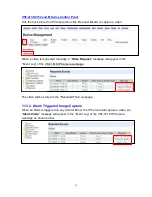
Page 62: ...manually request a video through the Control Panel The length of captured video is determined by the IP Camera s setting The factory default video length is 30 seconds with 10 seconds of pre alarm activation video and 20 seconds of post alarm activation video Please refer to 5 IP Camera 5 6 Alarm Setting to change the default setting 11 3 1 Video Request HPGW Series Control Panel Under the panel s...

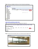
Page 63: ...appear in the Event Log of the VST 1818 IP Camera webpage The video will be stored in the Recorded Files webpage 11 3 2 Alarm Triggered Image Capture When an alarm is triggered on any Control Panel the IP Camera will capture a video An Alarm Video message will appear in the Event Log of the VST 1818 IP Camera webpage as shown below The video will be stored in the Recorded Files webpage ...

Page 64: ...on Detection Upload refer to 5 IP Camera 5 4 Motion Detection the IP Camera will capture a video to upload upon motion detection A Motion Detected Video message will appear in the Event Log of the VST 1818 IP Camera webpage The video will be stored in the Recorded Files webpage ...

Page 65: ... view the streaming video by logging into the Control Panel s Home Portal Server Please refer to the Home Portal Server operation manual for further detail 12 Appendix 12 1 Contact ID Event Code 789 Region 1 Detection When motion detection region 1 detects a movement 788 Region 2 Detection When motion detection region 2 detects a movement ...

Reviews: