1
1. Application Overview
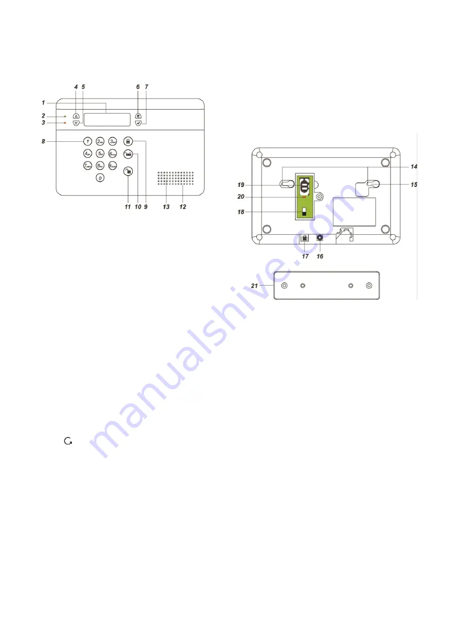
1.1. Identifying the Parts
1. Backlit LCD Display
2. Green LED
ON: AC Power is on.
FLASH: AC Power failure.
OFF: Power off
3. Yellow LED
ON: Fault Indicator; the Yellow LED will
light up when any fault situation is
detected and turn off when all fault
conditions are restored.
4.
Key
—
Use this key to move the cursor and
scroll the display upwards
5.
Key
—
Use this key to move the cursor and
scroll the display downwards.
6. Key
— Use this key for deleting a digit,
canceling the selection, aborting the
current screen and returning to the
previous screen etc.
7. OK Key
—
To confirm the keyed-in data or
confirm the selection.
8. Numeric Keys
9. Away Arm Key
— Use this key to Away Arm the system.
10.
Home Arm
Key
— Use this key to Home Arm the system.
11.
Disarm
Key
— Use this key to Disarm the system.
12. Buzzer
13. Microphone
14. Mounting Holes & Tamper
15. Tamper Switch
16. DC Jack
—
For connecting the DC 9V 1A power
adaptor.
17. Internet Connection (VST-2735/
VST-2752 Only)
18. Battery Switch
19. GSM/GPRS SIM Card Base (VST-
2745/ VST-2752 Only)
20. GSM/GPRS LED (VST-2745/VST-
2752 Only)
—
On for 5 seconds when power is
supplied.
—
Flash Slowly: GSM normal.
—
Flash Quickly: GSM failure.
21. Wall Mounting Bracket
—
For mounting the Control Panel on
the wall.


