
climecon.fi
© Climecon
1
Installation guide ECO4
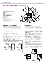
Parts of the air-forced heater ECO4
1.
Rear part, collar, heating element, electronic part and contacts for
supply voltage (230V) and for the thermostat cabling
2.
Perforated cover
3.
Fixing screw for the perforated cover (2 pcs)
4.
Fixing screw for the rear part (to a wall, 4 pcs)
Installation of the air-forced heater ECO4
1.
Drill holes into the wall for wires and fixing screws (4), using the
cutout template supplied with the delivery (for the cutout template
see Appendix 1).
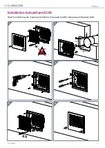
2.
The minimum distance of the supply air unit from the ceiling is
10 mm (see Figure 1.1). The minimum installation height from the
floor is 1,8 m. The diffuser must be installed in a place where children
can’t touch it without supervision.
3.
Pull the cover away from the rear part (1).
4.
Push the collar of the rear part inside the supply air duct and fix the
rear part to the wall, using four screws (4), Ø max 5 mm.
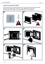
5.
Connect the supply cable of the supply air unit (MMJ) and the control
cable of the thermostat (KLMA) to the terminals of the electronic
part of the supply air unit as shown on Figure 2.
6.
Check that all the connections are correct. Push the perforated cover
back onto the rear part and fix it properly using the fixing screws of
the cover.
7.
Mark the power switch and temperature drop function switch clearly.
Connection
1.
Connect supply voltage (230V) to terminals N and L of the electronic
part of the supply air unit as shown on Figure 2.
2.
Connect the grounding to the separate ground terminal in the supply
air unit as shown on Figure 2.
3.
Connect the supply air unit of the ECO series to the thermostat by
means of the KLMA cable as shown on Figure 2.
4.
You can activate temperature drop function by connecting terminals
Z1 and G0 in the thermostat as shown on figure 5.
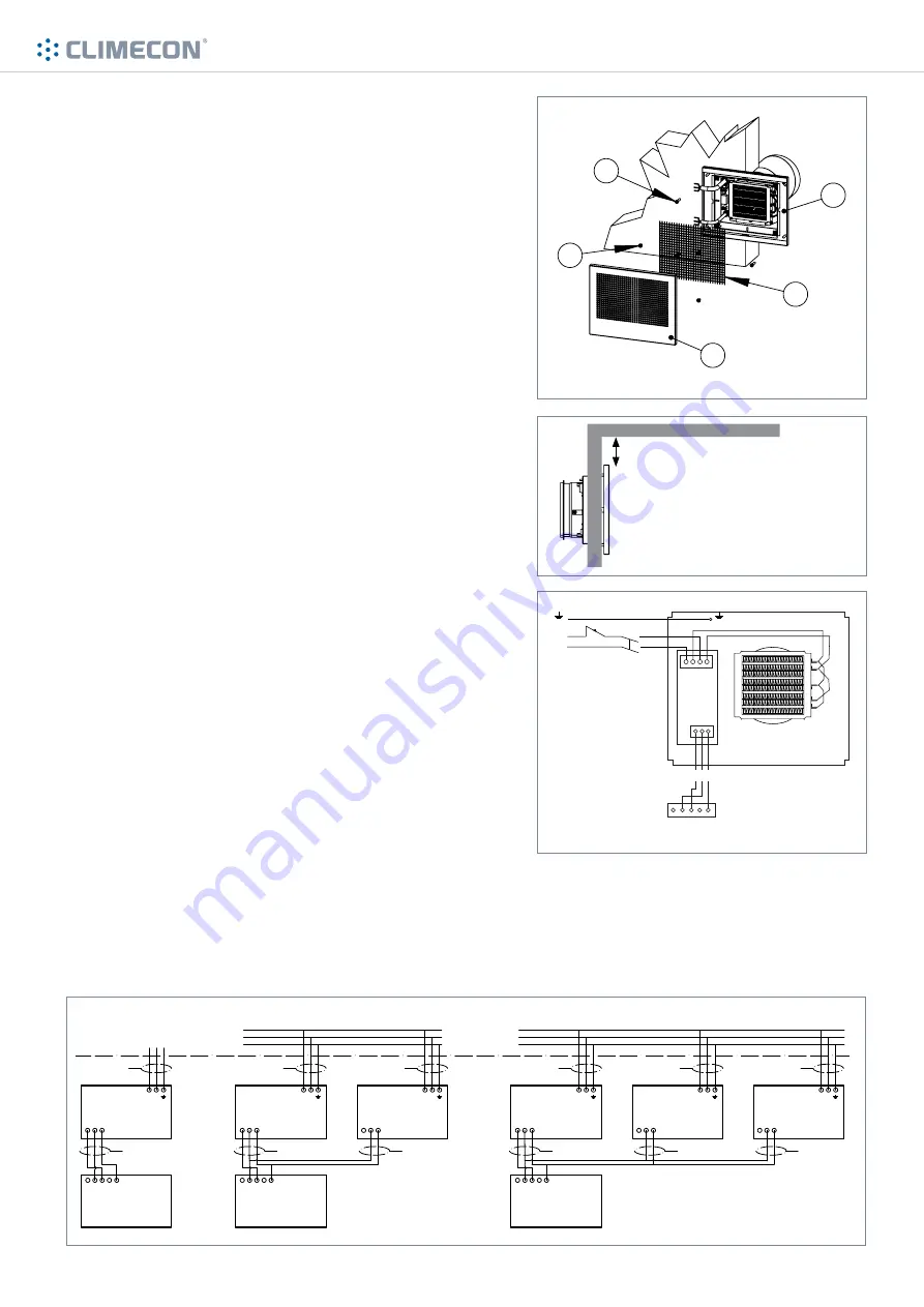
5.
When two or more forced-air heaters are controlled with one regu-
lating unit, the G pole of the power unit in only one supply air unit is
connected. The poles G0 and A2 are again connected from all con-
trolled power units. The supply air devices must be connected in the
same phase in the distribution box.
Note! Connection may be performed only by
a person with necessary professional skills.
WARNING! 230V voltage inside the unit.
U = 230V
I
n
= 2,4 A
I
A
= 3,7 A
1
2
3
5
4
NNLL
L
N
GO
G A2
Z1 G A2
G0 A1
24 VAC
230 VAC
ECO
Thermostat
ECO
Air-forced Heater
ECO4 distance from the ceiling
Min. 10 mm
Cabling modes of the ECO heating system
An all-pole switch must be used on the connection cable. All-pole switch with at least 3mm contact opening shall be used.
Figure 1
Figure 1.2
Figure 2
Figure 3
11.
13
ECOT REGULATOR
Z1G0 G A1 A2
ECO Supply Air Unit
G G0 A2
KLMA
3x0.8+0.8
L N
MMJ
3xX,XS
USE TYPE C CIRCUIT BREAKERS
ECOT REGULATOR
Z1G0 G A1 A2
ECO Supply Air Unit
G G0 A2
KLMA
3x0.8+0.8
L N
MMJ
3xX,XS
ECO Supply Air Unit
G G0 A2
L N
MMJ
3xX,XS
KLMA
2x0.8
ECOT REGULATOR
Z1G0 G A1 A2
ECO Supply Air Unit
G G0 A2
KLMA
3x0.8+0.8
L N
MMJ
3xX,XS
ECO Supply Air Unit
G G0 A2
L N
MMJ
3xX,XS
KLMA
2x0.8
ECO Supply Air Unit
G G0 A2
L N
MMJ
3xX,XS
KLMA
2x0.8
Figure 3


