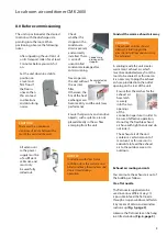
9.0 Commissioning
Before every commissioning the air
inlet and outlet openings should
be checked for foreign bodies and
the air inlet filter must be checked
for dirt. Blocked or soiled grills and
filters must be cleaned immediately,
see "Care and maintenance"
chapter.
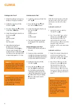
Cooling mode
1. Switch the unit on with the
"On/Off" key.
2. Select cooling mode with the
"MODE" key.
The "COOL" LED must illuminate.
3. Set the desired target
temperature with the
"Temperature setting" key. The
selected target temperature will
be shown in the display. If the
fan speed selected is too large
or too small then this can be
adjusted with the "FAN" key.
Recirculation mode
1. Switch the unit on with the
"On/Off" key.
2. Select ventilation mode with the
"FAN" key.
The "FAN" LED must illuminate.
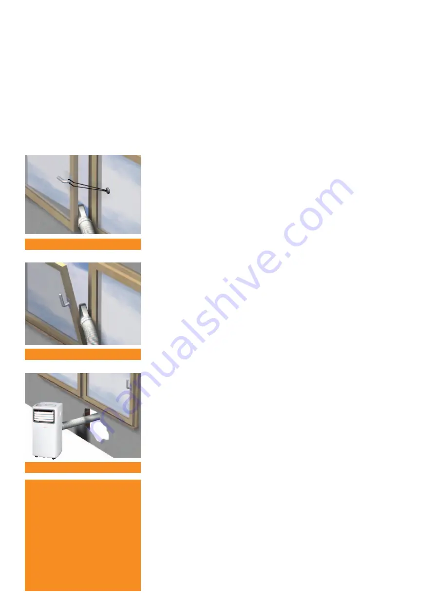
Via a wall pass-through
The hose supplied is firmly attached
to a wall pass-through. A suitable
wall pass-through is available as an
accessory
(Fig. 7)
.
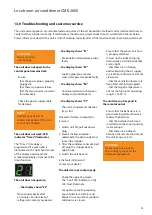
10.0 Shutdown
Temporary shutdown
If it is planned to shut down the unit
for longer periods e.g. during the
winter, proceed as follows:
1. Let the unit run in recirculating
operation for ca. 2 hours in
order to dry the surfaces of
the evaporator fins. This will
transport the remaining
moisture out of the unit and this
will avoid unpleasant odours
when the unit is
re-commissioned.
2. Switch the unit off with the
"On/Off" key, pull out the
power plug and wind up the
power supply cable. Ensure that
the cable is not kinked or too
severely bent.
3. Place a suitable container
underneath the condensate
drain of the internal reservoir.
The condensate drain is located
on the lower rear side of the unit.
4. Pull out the stopper from the
condensate drain and collect the
condensate that drains out.
5. Then insert the stopper once
again.
A missing stopper or an
incorrectly inserted stopper will
result in condensate leaking out
after re-commissioning.
6. Store the unit in an upright
position in a cool, dry and dust-
free location protected from
direct sunlight. Cover the unit
with a synthetic cover to protect
it against dust if desired.
NOTE
In some circumstances routing
the exhaust air via a firmly
attached exhaust air hose,
e.g. through closed doors or
windows, can lead to negative
pressure in the room in which the
unit is being used. If this should
reduce the performance of the
unit then arrange for the pressure
to be equalised.
Fig. 5
Exhaust air with open window
Fig. 6
Exhaust air with tilted window
Fig. 7
Wall pass-through
CLIMIA
10
Summary of Contents for CMK 2600
Page 1: ...Edition 3 0 English CLIMIA Local room air conditioner CMK 2600 Operating manual ...
Page 2: ...CLIMIA ...
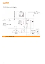
Page 14: ...15 0 Electrical wiring diagram Fig 12 Connection diagram CMK 2600 CLIMIA 14 ...
Page 19: ......
Page 20: ...Intakt GmbH Climia Klima und Wärmetechnik Niemeierstraße 13 D 32758 Detmold ...

