background image

1.3, with a tolerance of ± 5%.

2.1 

BOILER ROOM

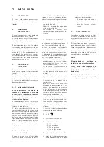
The  boiler  room  should  feature  all  the 
characteristics  required  by  standards 
governing liquid fuel heating systems.

2.2 

BOILER ROOM DIMENSIONS

Position  the  boiler  body  on  the  founda-
tion bed, which should be at least 10 cm 
high. The body should rest on a surface 
allowing  shifting,  possibly  by  means  of 
sheet metal. 
Leave  a  clearance  between  the  boiler 
and  the  wall  of  at  least  0.60  m,  and 
between  the  top  of  the  casing  and  the 
ceiling of 1 m (0.50 m in the case of boil-
ers  with  incorporated  D.H.W.  tank).  The 
ceiling height of the boiler room should 
not be less than 2.5 m.

2.3 

CONNECTING UP SYSTEM

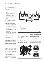
When  connecting  up  the  water  supply 
to the boiler, make sure that the speci-
fications  given  in  fig.  1  are  observed. 
All connecting unions should be easy to 
disconnect by means of tightening rings. 
A  closed  expansion  tank  system  must 
be used.

2.3.1  Filling the water system

Before connecting the boiler, thorough-
ly  flush  the  system  to  eliminate  scale 
which could damage the appliance.

Filling must be done slowly to allow any 
air bubbles to be bled off through the air 
valves. 
In  closed-circuit  heating  systems,  the 
cold water filling pressure and the pre-
charging pressure of the expansion ves-
sel should be no less than or equal to the 
height  of  the  water  head  of  the  instal-
lation  (e.g.  for  water  head  of  5  meters, 
the  vessel  pre-charging  pressure  and 
installation filling pressure should be at 
least 0.5 bar).

2.3.2  Characteristics of feedwater

Water supplying the heating circuit must 
be  treated  in  accordance  with  UNI-CTI 
8065 standards.
It  is  absolutely  essential  to  treat  water 
in  the  heating  system  in  the  following 
cases: 

–  For extensive systems (with high con-

tents of water).

–  Frequent addition of water into the sys-

tem.

–  Should  it  be  necessary  to  empty  the 

system either partially or totally.

2.4 

CONNECTING UP FLUE

The flue is of fundamental importance for 
the  proper  operation  of  the  boiler;  if  not 
installed  in  compliance  with  the  stand-
ards,  starting  the  boiler  will  be  difficult 
and there will be a consequent formation 
of soot, condensate and encrustation. 
The  flue  used  to  expel  combustion  prod-
ucts  into  the  atmosphere  must  meet  the 
following requirements:

–  be constructed with waterproof mate-

rials, and resistant to smoke tempera-
ture and condensate;

–  be  of  adequate  mechanical  resilience 

and of low heat conductivity;

–  be perfectly sealed to prevent cooling 

of the flue itself;

–  be as vertical as possible; the terminal 

section of the flue must be fitted with 
a  static  exhaust  device  that  ensures 
constant  and  efficient  extraction  of 
products generated by combustion;

–  to  prevent  the  wind  from  creating 

pressure  zones  around  the  chimney 
top  greater  than  the  uplift  force  of 
combustion  gases,  the  exhaust  out-
let  should  be  at  least  0.4  m  higher 
than  structures  adjacent  to  the  stack  
(including the roof top) within 8 m;

–  have  a  diameter  that  is  not  inferior 

to  that  of  the  boiler  union:  square  or 
rectangular-section flues should have 
an  internal  section  10%  greater  than 
that of the boiler union;

–  the  useful  section  of  the  flue  must 

conform to the following formula:


  S  resulting section in cm

2

K  reduction  coefficient  for  liquid 

fuels:


–  0.045 for firewood 


–  0.030 for coal


–  0.024 for light oil 


–  0.016 for gas

 
  P  boiler input in kcal/h
 
  H  height of flue in meters, measured 

from  the  flame  axis  to  the  top  of 
the flue reduced by:


–  0.50 m for each change of direc-

tion  of  the  connection  union 
between boiler and flue;


–  1.00 m for each metre of union 

itself.

2.5 

ELECTRICAL CONNECTION

The  boiler  is  fitted  with  an  electricity 
cable, and requires a 1ph - 230V - 50Hz 
power  supply  through  the  main  switch 
protected by fuses. 
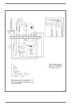
The  room  thermostat  (required  for 
enhanced  room  temperature  control) 
should be installed as shown in fig. 6. 
Connect  the  burner  with  the  cable  sup-
plied.

NO TE:  Device  must  be  connected  to  an 
efficient earthing system. 
CLIMIT  de cli nes  all  responsibility  for 
injury caused to persons due to failure 
to earth the boiler.  Always turn off the 
power supply before doing any work on 
the electrical panel. 

26


P

  S  =  K


H

2  INSTALLATION

Summary of Contents for GG E 3

Page 1: ...GG E 3 7 Cod 6276052A 07 2019 IT ES ENG FR RUS ...

Page 2: ...veglianza oppure dopo che le stesse abbiano ricevuto istruzioni relative all uso sicuro dell apparecchio e alla comprensione dei pericoli ad esso inerenti I bambini non devono giocare con l apparecchio La pulizia e la manutenzione destinata ad essere effettuata dall utilizzatore non deve essere effettuata da bambini senza sorveglianza INDICE 1 DESCRIZIONE DELL APPARECCHIO 1 1 INTRODUZIONE 1 1 2 DI...

Page 3: ...con una combustio ne perfettamente equilibrata e gli elevati rendimenti consentono di realizzare co spicui risparmi nei costi di esercizio 1 1 DESCRIZIONE DELL APPARECCHIO 1 2 DIMENSIONI Fig 1 GG E 3 4 5 6 7 P Profondità 415 515 615 715 815 M Mandata impianto 11 4 11 4 11 4 11 4 11 4 R Ritorno impianto 11 4 11 4 11 4 11 4 11 4 S Scarico caldaia 1 2 1 2 1 2 1 2 1 2 ...

Page 4: ...85 30 85 30 85 Peso kg 109 135 161 186 212 Con t 10 C Dati tecnici GG E Funzionamento con bruciatore a basse emissioni inquinanti NOx Classe 3 3 4 5 6 7 Potenza termica Minima kW 18 0 27 5 36 2 45 0 Massima kW 19 7 27 6 32 8 45 7 55 1 Portata termica Minima kW 20 0 30 5 40 0 49 6 Massima kW 21 9 30 7 36 3 50 5 60 7 Elementi di ghisa n 3 4 5 6 7 Pressione massima esercizio bar 4 4 4 4 4 Contenuto a...

Page 5: ...3 1 4 PERDITE DI CARICO CIRCUITO CALDAIA Fig 2 GG E 7 GG E 6 GG E 5 GG E 4 GG E 3 ...

Page 6: ...azione P min P max ø ø P min P max bar bar GG E 3 RG0 1R DELAVAN 0 50 0 60 60 W 60 W 11 5 12 0 R2000 G26 R DANFOSS 0 50 0 55 60 S 60 S 10 5 12 0 GG E 4 RG1R DELAVAN 0 65 0 75 80 W 60 W 12 5 13 0 R2000 G38 R DELAVAN 0 60 0 75 80 W 60 W 13 0 12 5 GG E 5 RG1R DELAVAN 0 85 1 00 60 W 60 W 11 5 11 5 R2000 G46 R DELAVAN 0 75 0 85 80 W 60 W 13 9 14 0 GG E 6 RG2 DELAVAN 1 00 1 10 60 W 60 W 10 0 10 0 R2000 ...

Page 7: ...se non è eseguita con gli opportuni criteri si possono avere di sfunzioni nel bruciatore amplificazioni di rumori formazioni di fuliggine conden sazioni e incrostazioni La canna fuma ria deve pertanto rispondere ai seguenti requisiti deve essere di materiale impermea bile e resistente alla temperatura dei fumi e relative condensazioni deve essere di sufficiente resistenza meccanica e di debole con...

Page 8: ...ruciatore alimentazione permanente non di fornitura TA Cronotermostato OP Orologio programmatore optional NOTE Collegando il cronotermostato TA togliere il ponte tra i morsetti 4 5 Collegando l orologio programmatore OP togliere il ponte tra i morsetti 5 8 Fig 6 ATTENZIONE Il cavo colore mar rone isolato si utilizza esclusi vamente per il collegamento di bruciatori con alimentazione per manente ti...

Page 9: ...Il valore della temperatura impostata si controlla sul termometro 4 impostare la temperatura del sanitario agendo sul termostato del bollitore 6 Il valore della temperatura impostata si controlla sul termometro 7 3 2 2 Termostato sicurezza fig 7 Il termostato sicurezza a riarmo manua le 2 interviene provocando l immediato spegnimento del bruciatore quando la temperatura in caldaia supera i 100 C P...

Page 10: ...pparecchiatura di comando e con trollo All accendersi di questo segnale il bru ciatore potrà funzionare nuovamente solo dopo aver premuto a fondo il pul sante di sblocco fatto ciò se avviene un accensione regolare si può imputare l arresto ad un anomalia transitoria e non pericolosa Al contrario se il blocco persiste si dovrà ricercare la causa dell anomalia e attua re i rimedi illustrati di segui...

Page 11: ...é il luogo di installazio ne della caldaia siano sufficientemente riscaldati caso contrario sia la caldaia che l impianto devono essere svuotati completamente Per uno svuotamento completo si deve eliminare anche il contenuto del bollitore e del serpentino di riscaldamento del bollitore 3 5 AVVERTENZE PER L UTENTE In caso di guasto e o cattivo funzio namento dell apparecchio disattivarlo astenendos...

Page 12: ...10 NOTE ...

Page 13: ...rios siempre que estén supervisados o después de haber recibido instrucciones relativas al uso seguro del aparato y comprensión de los peligros inherentes al mismo Los niños no deben jugar con el aparato La limpieza y el mantenimiento previstos por el usuario no deben ser reali zados por niños sin supervisión INDICE 1 DESCRIPCION DE LA CALDERA 1 1 INTRODUCCION 12 1 2 DIMENSIONES 1 3 DATOS TECNICOS...

Page 14: ...on gasóleo con una combustión perfecta mente equilibrada y los muy altos rendi mientos permiten conseguir importantes ahorros de combustible 1 DESCRIPCION DE LA CALDERA 1 2 DIMENSIONES Fig 1 GG E 3 4 5 6 7 P Profundidad 415 515 615 715 815 M Ida instalación 11 4 11 4 11 4 11 4 11 4 R Retorno instalación 11 4 11 4 11 4 11 4 11 4 S Descarga caldera 1 2 1 2 1 2 1 2 1 2 ...

Page 15: ...facción C 30 85 30 85 30 85 30 85 30 85 Peso kg 109 135 161 186 212 Con t 10 C Datos técnicos GG E NOx Clase 3 Quemador a bajas emisiones contaminantes 3 4 5 6 7 Potencia térmica Mínima kW 18 0 27 5 36 2 45 0 Máxima kW 19 7 27 6 32 8 45 7 55 1 Caudal térmico Mínimo kW 20 0 30 5 40 0 49 6 Máximo kW 21 9 30 7 36 3 50 5 60 7 Elementos n 3 4 5 6 7 Presión máx de servicio bar 4 4 4 4 4 Contenido de agu...

Page 16: ...14 1 4 PERDIDAS DE CARGA Fig 2 Loss of head mbar CAUDAL l h GG E 7 GG E 6 GG E 5 GG E 4 GG E 3 ...

Page 17: ...P máx bar bar GG E 3 RG0 1R DELAVAN 0 50 0 60 60 W 60 W 11 5 12 0 R2000 G26 R DANFOSS 0 50 0 55 60 S 60 S 10 5 12 0 GG E 4 RG1R DELAVAN 0 65 0 75 80 W 60 W 12 5 13 0 R2000 G38 R DELAVAN 0 60 0 75 80 W 60 W 13 0 12 5 GG E 5 RG1R DELAVAN 0 85 1 00 60 W 60 W 11 5 11 5 R2000 G46 R DELAVAN 0 75 0 85 80 W 60 W 13 9 14 0 GG E 6 RG2 DELAVAN 1 00 1 10 60 W 60 W 10 0 10 0 R2000 G120 DELAVAN 1 10 60 W 12 0 G...

Page 18: ... fundamental para el buen funcionamiento de la caldera En efecto si no se ejecuta conforme a las normas podría provocar problemas de arranque lo que implicaria formación de hollín condensaciones e incrustaciones El tubo de la chimenea debe por tanto respetar los reglamentos locales vigen tes y los siguientes requisitos estar realizado por materiales imper meables aptos para resistir a la tem perat...

Page 19: ...ntación permanente no incluido TA Termóstato ambiente OP Reloj de programación opcional NOTAS Si se conecta el termóstato ambiente TA se debe quitar el puente entre los bornes 4 5 Si se conecta el reloj de programación OP se debe quitar el puente entre los bornes 5 8 Fig 6 ATENCIÓN El cable de color marrón aislado se utiliza exclusivamente para la conexión de quemadores con alimentación permanente...

Page 20: ...ermóme tro 4 programar la temperatura del sani tario sobre el termóstato acumulador 6 El valor de la temperatura estable cida se controla sobre el termómetro 7 3 2 2 Termóstato de seguridad fig 7 El termóstato de seguridad de rear me manual 2 interviene provocando el inmediato apagado del quemador cuan do en la caldera se superan i 100 C Para volver a encender la caldera es necesa rio destornillar...

Page 21: ...ite la tapa de la envolvente 12 fi jada por medio de pivotes de acopla miento quite el panel 8 fijado a los laterales por medio de pivotes de acoplamiento quite el panel de mando 9 bloqueado a los laterales con cuatro tornillos au torroscantes quite los panelos traseros 6 y 7 fi jados a los laterales con diez tornillos autorroscantes desmonte el lateral izquierdo 3 destor nillando los tornillos qu...

Page 22: ...nación la regulación las prestaciones del quemador la temperatura preregulada el correcto funcionamiento y ubicación del ter móstato de regulación Asegúrarse que el generador sea de potencia suficiente para la instalación Olor de productos no incombustible Verifique la limpieza del cuerpo generador y de la evacuación de los humos lo hermético del generador y de los conductos de evacuación puer ta ...

Page 23: ...s long as they are supervised or after they have received instructions relating to the safe use of the appliance and an understanding of the dangers inherent to it Children must not play with the appliance Cleaning and maintenance intended to be carried out by the user must not be carried out by unsupervised children CONTENTS 1 BOILER DESCRIPTION 1 1 INTRODUCTION 22 1 2 DIMENSIONAL DETAILS 1 3 TEC...

Page 24: ...nd 92 42 CEE They use light oil and have a perfectly balanced combustion with a very high thermal efficiency for economical per formance 1 BOILER DESCRIPTION 1 2 DIMENSIONAL DETAILS Fig 1 GG E 3 4 5 6 7 P Depth 415 515 615 715 815 M C H flow 11 4 11 4 11 4 11 4 11 4 R C H return 11 4 11 4 11 4 11 4 11 4 S Boiler drain 1 2 1 2 1 2 1 2 1 2 ...

Page 25: ...e C 30 85 30 85 30 85 30 85 30 85 Weight kg 109 135 161 186 212 With t 10 C GG E technical features NOx Class 3 Burner with low polluting emissions 3 4 5 6 7 Output Minimum kW 18 0 27 5 36 2 45 0 Maximum kW 19 7 27 6 32 8 45 7 55 1 Input Minimum kW 20 0 30 5 40 0 49 6 Maximum kW 21 9 30 7 36 3 50 5 60 7 Sections n 3 4 5 6 7 Maximum water head bar 4 4 4 4 4 Water content l 12 8 16 8 20 8 24 8 28 8 ...

Page 26: ...24 1 4 LOSS OF HEAD Fig 2 Loss of head mbar Flow l h GG E 7 GG E 6 GG E 5 GG E 4 GG E 3 ...

Page 27: ... min P max bar bar GG E 3 RG0 1R DELAVAN 0 50 0 60 60 W 60 W 11 5 12 0 R2000 G26 R DANFOSS 0 50 0 55 60 S 60 S 10 5 12 0 GG E 4 RG1R DELAVAN 0 65 0 75 80 W 60 W 12 5 13 0 R2000 G38 R DELAVAN 0 60 0 75 80 W 60 W 13 0 12 5 GG E 5 RG1R DELAVAN 0 85 1 00 60 W 60 W 11 5 11 5 R2000 G46 R DELAVAN 0 75 0 85 80 W 60 W 13 9 14 0 GG E 6 RG2 DELAVAN 1 00 1 10 60 W 60 W 10 0 10 0 R2000 G120 DELAVAN 1 10 60 W 1...

Page 28: ...iler if not installed in compliance with the stand ards starting the boiler will be difficult and there will be a consequent formation of soot condensate and encrustation The flue used to expel combustion prod ucts into the atmosphere must meet the following requirements be constructed with waterproof mate rials and resistant to smoke tempera ture and condensate be of adequate mechanical resilienc...

Page 29: ...t Feeding Burner not supplied TA Room stat OP Programmer s clock optional NOTE When a room stat is to be fitted remove the link between terminal 4 and 5 on the connector plug To connect the programmer s clock OP remove the link between terminals 5 and 8 NOTE The brown capped off cable has to be exclusively used in case of permanent feeding burners type B1 ...

Page 30: ...er and press the button underneath If the problem occurs frequently call an authorised technical assistance centre for the necessary checks to be carried out 3 2 3 System filling Periodically check the pressure values of the hydrometer mounted onto the system when the system is cold should range between 1 and 1 2 bar If the pres sure is less than 1 bar reset the system 3 2 4 Turnig OFF boiler fig ...

Page 31: ... 1 disassemble the right side 4 fol lowing the same operations 3 3 3 Fault finding Herefater we outline a number of poten tial problems that may occur on the appliance and the relevant list of actions required A working fault in most cases provo cates the lock out signal onto the con trol panel of the control box When this light turns on the burner can operate again only after the reset button has...

Page 32: ...e regulation stat Make sure that the boiler is sufficiently powerful for the appliance Smell of unburnt products Control the cleanness of the boiler shell and the flue the airtightness of the boiler and of the flue ducts door combustion chamber smoke ducts flue washers Control the quality of the fuel Frequent intervention of the boiler shutoff valve Control the presence of air in the system the fu...

Page 33: ...s long as they are supervised or after they have received instructions relating to the safe use of the appliance and an understanding of the dangers inherent to it Children must not play with the appliance Cleaning and maintenance intended to be carried out by the user must not be carried out by unsupervised children CONTENTS 1 BOILER DESCRIPTION 1 1 INTRODUCTION 22 1 2 DIMENSIONAL DETAILS 1 3 TEC...

Page 34: ...nd 92 42 CEE They use light oil and have a perfectly balanced combustion with a very high thermal efficiency for economical per formance 1 BOILER DESCRIPTION 1 2 DIMENSIONAL DETAILS Fig 1 GG E 3 4 5 6 7 P Depth 415 515 615 715 815 M C H flow 11 4 11 4 11 4 11 4 11 4 R C H return 11 4 11 4 11 4 11 4 11 4 S Boiler drain 1 2 1 2 1 2 1 2 1 2 ...

Page 35: ...e C 30 85 30 85 30 85 30 85 30 85 Weight kg 109 135 161 186 212 With t 10 C GG E technical features NOx Class 3 Burner with low polluting emissions 3 4 5 6 7 Output Minimum kW 18 0 27 5 36 2 45 0 Maximum kW 19 7 27 6 32 8 45 7 55 1 Input Minimum kW 20 0 30 5 40 0 49 6 Maximum kW 21 9 30 7 36 3 50 5 60 7 Sections n 3 4 5 6 7 Maximum water head bar 4 4 4 4 4 Water content l 12 8 16 8 20 8 24 8 28 8 ...

Page 36: ...24 1 4 LOSS OF HEAD Fig 2 Loss of head mbar Flow l h GG E 7 GG E 6 GG E 5 GG E 4 GG E 3 ...

Page 37: ... min P max bar bar GG E 3 RG0 1R DELAVAN 0 50 0 60 60 W 60 W 11 5 12 0 R2000 G26 R DANFOSS 0 50 0 55 60 S 60 S 10 5 12 0 GG E 4 RG1R DELAVAN 0 65 0 75 80 W 60 W 12 5 13 0 R2000 G38 R DELAVAN 0 60 0 75 80 W 60 W 13 0 12 5 GG E 5 RG1R DELAVAN 0 85 1 00 60 W 60 W 11 5 11 5 R2000 G46 R DELAVAN 0 75 0 85 80 W 60 W 13 9 14 0 GG E 6 RG2 DELAVAN 1 00 1 10 60 W 60 W 10 0 10 0 R2000 G120 DELAVAN 1 10 60 W 1...

Page 38: ...iler if not installed in compliance with the stand ards starting the boiler will be difficult and there will be a consequent formation of soot condensate and encrustation The flue used to expel combustion prod ucts into the atmosphere must meet the following requirements be constructed with waterproof mate rials and resistant to smoke tempera ture and condensate be of adequate mechanical resilienc...

Page 39: ...t Feeding Burner not supplied TA Room stat OP Programmer s clock optional NOTE When a room stat is to be fitted remove the link between terminal 4 and 5 on the connector plug To connect the programmer s clock OP remove the link between terminals 5 and 8 NOTE The brown capped off cable has to be exclusively used in case of permanent feeding burners type B1 ...

Page 40: ...er and press the button underneath If the problem occurs frequently call an authorised technical assistance centre for the necessary checks to be carried out 3 2 3 System filling Periodically check the pressure values of the hydrometer mounted onto the system when the system is cold should range between 1 and 1 2 bar If the pres sure is less than 1 bar reset the system 3 2 4 Turnig OFF boiler fig ...

Page 41: ... 1 disassemble the right side 4 fol lowing the same operations 3 3 3 Fault finding Herefater we outline a number of poten tial problems that may occur on the appliance and the relevant list of actions required A working fault in most cases provo cates the lock out signal onto the con trol panel of the control box When this light turns on the burner can operate again only after the reset button has...

Page 42: ...e regulation stat Make sure that the boiler is sufficiently powerful for the appliance Smell of unburnt products Control the cleanness of the boiler shell and the flue the airtightness of the boiler and of the flue ducts door combustion chamber smoke ducts flue washers Control the quality of the fuel Frequent intervention of the boiler shutoff valve Control the presence of air in the system the fu...

Page 43: ... qu elles aient reçu les instructions relatives à l utilisation en toute sécurité de l appareil et une compréhension des dangers inhérents à celui ci Les enfants ne doivent pas jouer avec l appareil Le nettoyage et l entretien destinés à être effectués par l utilisateur ne doivent pas être effectués par des enfants sans surveillance TABLES DES MATIÈRES 1 DESCRIPTION DE L APPAREIL 1 1 INTRODUCTION ...

Page 44: ...ombustion parfaitement équilibrée et son haut rendement permet de réaliser de grosses économies en ma tière de coûts de fonctionnement 1 DESCRIPTION DE L APPAREIL 1 2 DIMENSIONS Fig 1 GG E 3 4 5 6 7 P Profondeur 415 515 615 715 815 M Refoulement de l équipement 11 4 11 4 11 4 11 4 11 4 R Retour de l équipement 11 4 11 4 11 4 11 4 11 4 S Évacuation de la chaudière 1 2 1 2 1 2 1 2 1 2 ...

Page 45: ...5 30 85 30 85 30 85 30 85 Poids kg 109 135 161 186 212 Avec t 10 C Données techniques GG E Fonctionnement avec un brûleur à faibles émissions polluantes NOx Classe 3 3 4 5 6 7 Puissance thermique Minimum kW 18 0 27 5 36 2 45 0 Maximum kW 19 7 27 6 32 8 45 7 55 1 Débit calorifique Minimum kW 20 0 30 5 40 0 49 6 Maximum kW 21 9 30 7 36 3 50 5 60 7 Éléments en fonte n 3 4 5 6 7 Pression maximale de f...

Page 46: ...34 1 4 PERTES DE CHARGE DU CIRCUIT CHAUDIÈRE Fig 2 GG E 7 GG E 6 GG E 5 GG E 4 GG E 3 Pertes de charge mbar Débit l h ...

Page 47: ...sation P min P max ø ø P min P max bar bar GG E 3 RG0 1R DELAVAN 0 50 0 60 60 W 60 W 11 5 12 0 R2000 G26 R DANFOSS 0 50 0 55 60 S 60 S 10 5 12 0 GG E 4 RG1R DELAVAN 0 65 0 75 80 W 60 W 12 5 13 0 R2000 G38 R DELAVAN 0 60 0 75 80 W 60 W 13 0 12 5 GG E 5 RG1R DELAVAN 0 85 1 00 60 W 60 W 11 5 11 5 R2000 G46 R DELAVAN 0 75 0 85 80 W 60 W 13 9 14 0 GG E 6 RG2 DELAVAN 1 00 1 10 60 W 60 W 10 0 10 0 R2000 ...

Page 48: ...e augmenta tion de la nuisance sonore la formation de rouille de la condensation et des incrustations Le conduit de fumée doit donc être conforme aux prescriptions suivantes il doit être réalisé dans un matériau imperméable et résistant à la tempé rature des fumées et des condensats il doit posséder une résistance méca nique suffisante et une faible conducti vité de la chaleur il doit être parfait...

Page 49: ...Brûleur d alimentation permanente non fourni TA Thermostat programmable OP Horloge de programmation en option REMARQUES En branchant le thermostat programmable TA il faut enlever le pont entre les bornes 4 5 En branchant l horloge de programmation OP il faut enlever le pont entre les bornes 5 8 Fig 6 ATTENTION le câble marron isolé ne s utilise que pour le raccordement aux brûleurs à ali mentation...

Page 50: ...urée sur le thermomètre 4 Configurer la température de l eau chaude sanitaire en réglant le ther mostat de chauffe eau 6 Contrôler la valeur de la température configurée sur le thermomètre 7 3 2 2 Thermostat de sécurité fig 7 Le thermostat de sécurité à réarmement manuel 2 intervient en provoquant l ex tinction immédiate du brûleur quand la température dans la chaudière dépasse 100 C Pour rétablir...

Page 51: ...ntraîne l allumage de la signalisation de blocage de l appareil de commande et de contrôle Lorsque ce signal s allume le brûleur ne pourra fonctionner à nouveau qu après avoir appuyé à fond sur le bouton de dé blocage ceci étant fait si l allumage est régulier c est que l arrêt est dû à une anomalie transitoire sans danger En revanche si le blocage persiste il faut rechercher la cause de l anomali...

Page 52: ...stème de chauffage reste en marche et que les locaux ainsi que le lieu d installation de la chaudière soient suffisamment chauds sinon il faut entièrement vider la chaudière et le système Pour un vidage complet il faut éliminer aussi le contenu du chauffe eau et du serpentin de chauffage du bouilleur 3 5 MISES EN GARDE POUR L UTILISATEUR En cas de panne ou de dysfonction nement de l appareil le dé...

Page 53: ...ом или после того как они получили инструкции касающиеся безопасного использования устройства и понимание связанных с ним опасностей Не разрешайте детям играть с прибором Чистка и техническое обслуживание предназначенные для пользователя не должны выполняться детьми без присмотра Оглавление 1 Описание аппарата 1 1 Введение 42 1 2 Размеры 1 3 Технические данные 43 1 4 ПОТЕРИ НАГРУЗКИ 44 1 5 Камера ...

Page 54: ...4 35 EC TPTC 004 2011 Они работают на газойле с устойчивым горением их высокая производительность позволяет значительно сократить расходы по их эксплуатации 1 ОПИСАНИЕ АППАРАТА 1 2 Размеры Pис 1 GG E 3 4 5 6 7 P глубина 415 515 615 715 815 M подача под давлением в системе 11 4 11 4 11 4 11 4 11 4 R Racord retur 11 4 11 4 11 4 11 4 11 4 S Racord golire 1 2 1 2 1 2 1 2 1 2 ...

Page 55: ... 85 30 85 30 85 30 85 30 85 Вес кг 109 135 161 186 212 При t 10 C Технические данные GG E Функционирование с горелкой с низким уровнем загрязнения NОх класс 3 3 4 5 6 7 Тепловая мощность Минимальная кватт 18 0 27 5 36 2 45 0 Максимальная кватт 19 7 27 6 32 8 45 7 55 1 Производительность по теплу Минимальная кватт 20 0 30 5 40 0 49 6 Максимальная кватт 21 9 30 7 36 3 50 5 60 7 Элементы 3 4 5 6 7 Ма...

Page 56: ...44 1 4 ПОТЕРИ НАГРУЗКИ Pис 2 ПОТЕРИ НАГРУЗКИ p мБар Расход л час GG E 7 GG E 6 GG E 5 GG E 4 GG E 3 ...

Page 57: ... P макс ø ø P мин P макс Бар Бар GG E 3 RG0 1R DELAVAN 0 50 0 60 60 W 60 W 11 5 12 0 R2000 G26 R DANFOSS 0 50 0 55 60 S 60 S 10 5 12 0 GG E 4 RG1R DELAVAN 0 65 0 75 80 W 60 W 12 5 13 0 R2000 G38 R DELAVAN 0 60 0 75 80 W 60 W 13 0 12 5 GG E 5 RG1R DELAVAN 0 85 1 00 60 W 60 W 11 5 11 5 R2000 G46 R DELAVAN 0 75 0 85 80 W 60 W 13 9 14 0 GG E 6 RG2 DELAVAN 1 00 1 10 60 W 60 W 10 0 10 0 R2000 G120 DELAV...

Page 58: ...еленные критерии могут возникнуть неполадки в работе горелки усиление шумов появление копоти конденсата и накипеобразований Следовательно дымовая труба должна отвечать следующим требованиям она должна быть сделана из водонепроницаемого материала устойчивого к температуре дыма и следовательно к конденсации должна обладать достаточной сопротивляемостью механическим нагрузкам и слабой теплопроводност...

Page 59: ...лка с постоянной подачей не входит в поставку TA Климатический регулятор OP Программируемый таймер дополнительно Примечание При подключении хронотермостата TA снимите перемычку установленную на зажимы 4 5 При подключении программируемого таймера OP снимите перемычку установленную на зажимы 5 8 ВНИМАНИЕ Кабель коричневого цвета изолированный используется исключительно для подключения горелок с пост...

Page 60: ...рмометра 4 Установите температуру санитарной обработки при помощи термостата котла 6 Установленная величина температуры проверяется при помощи термометра 7 3 2 2 Защитный термостат рис 7 Защитный термостат с ручным перевооружением 2 срабатывает немедленно выключая горелку если температура в котлоагрегате поднимается выше 100 С Для возобновления функционирования котлоагрегата необходимо отвинтить ч...

Page 61: ...ю соединительных штырей снимите правую переднюю панель 8 прикрепленную к боковой стенке двумя винтами снимите пульт управления 9 прикрепленный к боковыи стенкам двумя самонарезающимися винтами снимите задние панели 6 и 7 прикрепленные к боковым стенкам десятью самонарезающимися винтами снимите левую боковую стенку 3 отвинтив винты которыми она прикрепляется к верхнему кронштейну 5 и отвинтите винт...

Page 62: ... корпус генератора спаренность регулировку возможности горелки предварительно установленную температуру правильное функционирование и позиционирование регулирующего термостата Убедитесь чтогенераторобладаетдостаточной мощностью для данной системы Запах несгоревшего газа Проверьте очищены ли корпус генератора и трубавыбросадыма герметичностьгенератора и труб выброса дверца камера горения дымовой ка...

Page 63: ...51 NOTE ...

Page 64: ...52 NOTE ...

Page 65: ......

Page 66: ...Via Garbo 27 37045 Legnago Vr Tel 39 0442 631111 Fax 39 0442 631292 ...

Reviews: