background image

26

CONSIGLI PRATICI DI INSTALLAZIONE

Posizionamento

-  Osservare scrupolosamente gli spazi di rispetto indicati a ca-

talogo.

-  Verificare  che  non  vi  siano  ostruzioni  sull’aspirazione  della 

batteria alettata e sulla mandata dei ventilatori.

-  Posizionare l’unità in modo da rendere minimo l’impatto ambien-

tale (emissione sonora, integrazione con le strutture presenti, 
ecc.).

Collegamenti elettrici

-  Consultare sempre lo schema elettrico incluso nel quaderno  

tecnico, ove sono sempre riportate tutte le istruzioni necessarie 
per effettuare i collegamenti elettrici.

-  Dare tensione all’unità (chiudendo il sezionatore) almeno 12 ore 

prima dell’avviamento, per permettere l’alimentazione delle re-
sistenze del carter. Non togliere tensione alle resistenze durante 
i brevi periodi di fermata dell’unità.

-  Prima di aprire il sezionatore fermare l’unità agendo sugli appositi 

interruttori di marcia, o in assenza sul comando a distanza.

-  Prima di accedere alle parti interne dell’unità, togliere tensione 

aprendo il sezionatore generale.

-  é vivamente raccomandata l’installazione di un interruttore ma-

gnetotermico a protezione della linea elettrica di alimentazione 
(a cura dell’installatore).

-  Collegamenti elettrici da effettuare:
 

 Cavo di potenza tri  terra;

-  Collegamenti elettrici opzionali da effettuare;
 

 Consenso esterno;


 Riporto allarme a distanza.

Collegamenti idraulici

-  Sfiatare accuratamente l’impianto idraulico, a pompe spente, 

agendo sulle valvoline di sfiato. Questa procedura è particolar-
mente importante in quanto anche piccole bolle d’aria possono 
causare il congelamento dell’evaporatore.

-  Scaricare,  se  necessario,  l’impianto  idrico  durante  le  soste 

invernali o usare appropriate miscele anticongelanti.

- Installare sempre un filtro a rete metallica sull'ingresso dell'unità 

a protezione dello scambiatore a piastre.

-  Realizzare il circuito idraulico includendo i componenti indicati 

negli  schemi  raccomandati  (vaso  di  espansione,  serbatoio 
d’accumulo, valvole di sfiato, valvole di intercettazione, valvola 
di taratura, giunti antivibranti, ecc.).

Avviamento e manutenzione

-  Attenersi scrupolosamente a quanto indicato nel manuale di 

uso e manutenzione. Tali operazioni devono comunque essere 
effettuate da personale qualificato.

INSTALLATION RECOMMENDATIONS

Location

-  Strictly allow clearances as indicated in the catalogue.

-  Ensure there are no obstructions on the air suction and discharge 

side.

-  Locate the unit in order to be compatible with environmental 

requirements (sound level, integration into the site, etc.).

Electrical connections

-  Check the wiring diagram enclosed with the unit, in wich are 

always present all the instructions necessary to the electrical 

connections.

-  Supply the unit at least 12 hours before start-up, in order to turn 

crankcase heaters on. Do not disconnect electrical supply during 

temporary stop periods (i.e. week-ends).

-  Before opening the main switch, stop the unit by acting on the 

suitable running switches or, if lacking, on the remote control.

-  Before  servicing  the  inner  components,  disconnect  electrical 

supply by opening the main switch.

-  The electrical supply line must be equipped with an automatic 

circuit breaker (to be provided by the installer).

-  Electrical connections to be done:

  ◊ Three-wire power cable + neutral cable + ground cable;

Optional electrical connections to be done;

  ◊ External interlock;

  ◊ Remote alarm signalling.

Hydraulic connections

-  Carefully vent the system, with pump turned off, by acting on 

the vent valves. this procedure is fundamental: little air bubbles 

can  freeze  the  evaporator  causing  the  general  failure  of  the 

system.

-  Drain  the  system  during  seasonal  stops  (wintertime)  or  use 

proper mixtures with low freezing point.

-  Always install a metallic filter on the unit inlet in order to protect 

the plate exchanger. 

-  Install the hydraulic circuit including all the components indicated 

in the recommended hydraulic circuit diagrams (expansion ves-

sel, storage tank, vent valves, balancing valve, shut off valves 

flexible connections, etc.).

Start up and maintenance operations

-  Strictly follow what reported in use and maintenance manual.  

All these operations must be carried on by trained personnel 

only.

Summary of Contents for CHA/K/FC 101

Page 1: ...IGKEITSKÜHLER FREIE KÜHLUNG MIT AXIALLÜFTER UND SCROLLVERDICHTERN VON 28 kW BIS 43 kW REFRIGERATORI D ACQUA ARIA ACQUA FREE COOLING CON VENTILATORI ASSIALI E COMPRESSORI SCROLL DA 28 kW A 43 kW WATER CHILLERS FREE COOLING WITH AXIAL FANS AND SCROLL COMPRESSORS FROM 28 kW TO 43 kW GROUPES D EAU GLACÉE FREE COOLING AVECVENTILATEURS AXIAUX ET COMPRESSEURS SCROLL DE 28 kW À 43 kW ...

Page 2: ... ...

Page 3: ...3 Explication de le diagrammes 24 Diagrammes électriques 25 Conseils pratiques pour l installation 27 INDICE Pag Descrizione generale 4 Versioni 4 Caratteristiche costruttive 4 Accessori montati in fabbrica 4 Accessori forniti separatamente 4 Risparmio energetico 6 Grafico 7 Principio di funzionamento 8 Funzionamento estivo 8 Funzionamento invernale 8 Funzionamento nelle stagioni intermedie 8 Vant...

Page 4: ...energia La gamma comprende 4 modelli che coprono potenzialità frigorifere da 28 a 43 kW Le unità CHA K FC sono particolarmente indicate nelle installazioni dove è richiesta la produzione di acqua refrigerata in servizio continuo e quindi anche con bassa temperatura esterna La funzione Free Cooling permette di ottenere un raffreddamento gratuito dell acqua di utilizzo per mezzo di una batteria ad a...

Page 5: ... et vernissage AG Antivibreurs en caoutchouc à insérer à la base de l unité pour estomper les vibrations éventuelles dues au type de sol sur lequel la machine est installée ALLGEMEINE EIGENSCHAFTEN Luftgekühlte Flüssigkeitskühler mit Axiallüftern und Frei Kühleinrich tung zur Energieeinsparung Zur Auswahl stehen 4 Modelle mit Kühl leistungen von 28 bis 43 kW Die CHA K FC Geräte eignen sich für den...

Page 6: ...l risparmio en ergetico attraverso le prestazioni del chiller free cooling confrontate con le prestazioni di un normale chiller Grafico A La curva n 1 è riferita al funzionamento di un normale chiller e mostra la potenza assorbita alle diverse condizioni di temperatura ambiente Lacurvan 2èriferitaagliassorbimentielettricidiunchillerfree cool ing alle diverse condizioni di temperatura ambiente ed è...

Page 7: ... 0 1 00 200 300 400 500 600 700 2 1 ...

Page 8: ...delle ore di funzionamento Minori spese di manutenzione OPERATING PRINCIPLE The Free Cooling series of refrigerating units are designed to cool a gly col water solution Besides the main components used on ordinary chillers such as com pressors condensers evaporator expansion valves these units also include a free cooling water coil A control system consisting of a 3 way modulating valve and a set ...

Page 9: ...s de frais de maintenance BEZEICHNUNG DESCRIPTION BEZEICHNUNG DESCRIPTION CA Luftgek Verflüssiger Condenseur SB Mikroprocessor Microprocesseur CAF Free Cooling Wärmetauscher Condenseur avec Free Cooling ST1 Temperaturfühler Sonde de travail EW Verdampfer Voyant liquide ST2 Frostschutzfühler Sonde anti gel MC Verdichter Compresseur ST3 Temperaturfühler Wassereintritt Sonde de l eau en entrée MV Axi...

Page 10: ...ta kW 0 98 0 98 1 96 1 96 Nominal input Carica refrigerante kg 6 1 8 9 9 1 9 2 Refrigerant charge Pressione sonora DIN 3 dB A 60 61 61 61 Sound pressure DIN 3 Pressione sonora ISO 4 dB A 51 52 52 52 Sound pressure ISO 4 Carica olio kg 3 3 3 3 3 3 3 6 Oil charge Contenuto acqua scambiatore dm 1 9 1 9 2 5 3 0 Heat exchanger water volume Portata acqua glicolata l s 1 55 1 74 2 07 2 37 Water flow Peso...

Page 11: ...1 96 Puissance installée Kältemittelfüllung kg 6 1 8 9 9 1 9 2 Charge refrigerant Schalldruckpegel DIN 3 dB A 60 61 61 61 Pression sonore DIN 3 Schalldruckpegel ISO 4 dB A 51 52 52 52 Pression sonore ISO 4 Ölfüllung kg 3 3 3 3 3 3 3 6 Charge d huile Wärmetauscher Wasservol dm 1 9 1 9 2 5 3 0 Volume d eau echangeur Wassermenge l s 1 55 1 74 2 07 2 37 Débit d eau Liefergewicht kg 415 430 470 485 Poi...

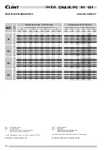
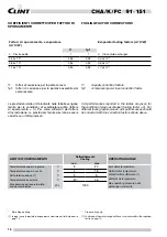
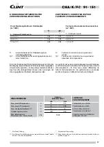
Page 12: ... 3 8 9 42 5 8 1 15 37 4 11 0 40 4 9 9 43 0 9 0 45 3 8 2 131 5 30 9 13 9 33 6 12 7 36 2 11 6 38 5 10 6 7 33 3 13 9 36 2 12 7 38 9 11 6 41 3 10 6 9 35 9 13 9 39 0 12 7 41 7 11 6 44 2 10 6 11 38 7 13 9 41 8 12 7 44 7 11 6 47 3 10 7 13 41 5 13 9 44 8 12 7 47 7 11 6 50 4 10 7 15 44 4 13 9 47 8 12 7 50 9 11 6 53 7 10 8 151 5 35 7 15 6 38 5 14 2 41 0 12 9 43 3 11 8 7 38 4 15 6 41 4 14 2 44 0 12 9 46 5 11...

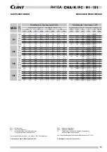
Page 13: ... 9 40 3 8 9 42 5 8 1 15 37 4 11 0 40 4 9 9 43 0 9 0 45 3 8 2 131 5 30 9 13 9 33 6 12 7 36 2 11 6 38 5 10 6 7 33 3 13 9 36 2 12 7 38 9 11 6 41 3 10 6 9 35 9 13 9 39 0 12 7 41 7 11 6 44 2 10 6 11 38 7 13 9 41 8 12 7 44 7 11 6 47 3 10 7 13 41 5 13 9 44 8 12 7 47 7 11 6 50 4 10 7 15 44 4 13 9 47 8 12 7 50 9 11 6 53 7 10 8 151 5 35 7 15 6 38 5 14 2 41 0 12 9 43 3 11 8 7 38 4 15 6 41 4 14 2 44 0 12 9 46...

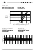
Page 14: ...ALE POMPA DI CIRCOLAZIONE CIRCULATION PUMP TOTAL STATIC PRESSURE PERTES DE CHARGE CIRCUIT HYDRAULIQUE GESAMTESTATISCHEN PRESSUNG DER UMLAUFPUMPE PRESSION TOTALE DE LA POMPE DE CIRCULATION WÄRMETAUSCHER DRUCKVERLUST E DES HYDRAULISCHEN KREISLAUFS 9 1 1 0 1 1 3 1 1 5 1 3 101 131 151 91 3 5 ...

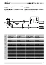
Page 15: ...ISTURE IND SIGTH GLASS FLÜSSIG FEUCHTIGKEIT SCHAUGLAS VOYANT LIQUIDE HUMIDITÉ SPH PRESSOSTATO ALTA MAN HIGH PRESS SWITCH M R HOCHDRUCKSCHALTERMAN PRSS HAUTE PRESS MAN SPL PRESSOSTATO BASSA AUT LOW PRESS SWITCH A R NIEDERDRUCKSCHALT AUT PRESS BASSE PRESS AUT SPS PRESSOSTATO COMANDO VS PRESSURE SWITCH VS REGOLATOR PRESSOSTAT PRESSOSTAT ST SERBATOIO STORAGE TANK SPEICHERBEHÄLTER BALLON TAMPON ST1 SON...

Page 16: ...orrected with the correction factors shown above Fattori di sporcamento evaporatore m C W Evaporator fouling factors m C W f1 fp1 0 Piastre pulite 1 1 0 Clean plate exchanger 0 44 x 10 4 0 98 0 99 0 44 x 10 4 0 88 x 10 4 0 96 0 99 0 88 x 10 4 1 76 x 10 4 0 93 0 98 1 76 x 10 4 LIMITI DI FUNZIONAMENTO Raffreddamento Cooling OPERATING RANGE min max Temperatura acqua in ingresso C 8 20 Inlet water tem...

Page 17: ... facteur d encrassements les performances annoncées seront corrigées en utilisant les facteurs indiqués Verschmutzungsfaktoren Verdampfer m C W Facteured encrassementeevaporateur m C W f1 fp1 0 Sauberer Wärmetauscher 1 1 0 Echangeur propre 0 44 x 10 4 0 98 0 99 0 44 x 10 4 0 88 x 10 4 0 96 0 99 0 88 x 10 4 1 76 x 10 4 0 93 0 98 1 76 x 10 4 EINSATZBEREICH Kühlung Refroidissement LIMITES DE FONCTION...

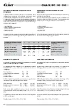
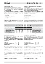
Page 18: ...valori facendo uso dei coefficienti riportati in tabella Resa frigorifera 31 4 x 0 946 29 7 kW Potenza assorbita compressore 10 0 x 0 995 9 95 kW Portata acqua 1 74 x 1 04 1 81 l s Dalla curva delle perdite di carico si ricava la perdita corrispondente al nuovo valore della portata 1 74 l s 152 kPa La perdita di carico corretta relativa ad una miscela di glicole al 50 sarà dunque Perdita di carico...

Page 19: ... GlykolundunterVerwendungderoben angeführten Koeffizienten ändern sich diese Werte wie folgt Kälteleistung 31 4 x 0 946 29 7 kW Compressor Leistungsaufnahme 10 0 x 0 995 9 95 kW Mischungsdurchfluß 1 74 x 1 04 1 81 l s Von der Druckverlust Kurve kann der dem neuen Durchflußwert entsprechende Druckverlust 1 74 l s 152 kPa abgelesen werden Der korrekte Druckverlust bezüglich einer 50 Glykolmischung w...

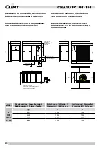
Page 20: ... Entrée eau Uscita acqua Water outlet Wasseraustritt Sortie eau kg Ø Ø 91 437 1 M 1 M 101 452 1 M 1 M 91 SP 667 1 M 1 M 101 SP 682 1 M 1 M 1850 900 1850 800 18 18 14 325 200 415 200 550 770 1700 1840 380 900 510 1290 50 1430 1847 ENTRATA LINEA ELETTRICA VOLTAGE SUPPLY INLET ENTREE ALIMENTATION ELETRIQUE ELEKTRISCHER ANSCHLUSS SORTIE EAU WASSERAUSTRITT WATER OUTLET USCITA ACQUA 1 M ENTREE EAU WASSE...

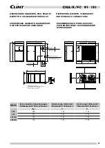
Page 21: ...t Entrée eau Uscita acqua Water outlet Wasseraustritt Sortie eau kg Ø Ø 131 499 1 M 1 M 151 515 1 M 1 M 131 SP 729 1 M 1 M 151 SP 745 1 M 1 M 1840 1700 900 550 1847 18 14 415 325 18 1850 770 380 1290 1850 510 800 900 50 1430 ELEKTRISCHER ANSCHLUSS ENTREE ALIMENTATION ELETRIQUE VOLTAGE SUPPLY INLET ENTRATA LINEA ELETTRICA 25 847 25 140 USCITA ACQUA WATER OUTLET WASSERAUSTRITT SORTIE EAU 1 M 23 120 ...

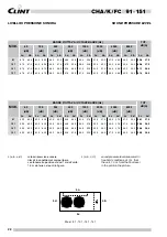
Page 22: ...9 9 57 9 101 61 0 61 0 63 0 60 0 55 5 57 5 57 0 53 5 56 5 52 5 52 5 50 0 48 0 46 0 48 5 48 0 60 6 57 9 131 61 5 61 0 63 5 61 0 56 0 58 0 57 5 54 5 57 0 53 0 53 0 51 0 48 5 46 0 49 0 48 0 61 1 58 6 151 61 5 61 0 63 5 61 0 56 0 58 0 57 5 55 0 57 5 53 5 53 0 51 0 48 5 46 5 49 0 48 0 61 3 58 9 MOD BANDE D OTTAVA OCTAVE BANDS Hz TOT dB A Lc Ld 63 125 250 500 1000 2000 4000 8000 dB dB dB dB dB dB dB dB ...

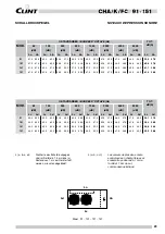
Page 23: ... 101 61 0 61 0 63 0 60 0 55 5 57 5 57 0 53 5 56 5 52 5 52 5 50 0 48 0 46 0 48 5 48 0 60 6 57 9 131 61 5 61 0 63 5 61 0 56 0 58 0 57 5 54 5 57 0 53 0 53 0 51 0 48 5 46 0 49 0 48 0 61 1 58 6 151 61 5 61 0 63 5 61 0 56 0 58 0 57 5 55 0 57 5 53 5 53 0 51 0 48 5 46 5 49 0 48 0 61 3 58 9 MOD OKTAVBÄNDER BANDES D OCTAVE Hz TOT dB A Lc Ld 63 125 250 500 1000 2000 4000 8000 dB dB dB dB dB dB dB dB Lc Ld Lc...

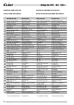
Page 24: ...ventilateur MC COMPRESSORE COMPRESSOR Verdichter Compresseur MP MOTORE POMPA PUMP MOTOR Pumpemotor Pompe MV1 MOTORE VENTILATORE FAN MOTOR Gebläse Ventilateurs MV2 MOTORE VENTILATORE 101 131 151 FAN MOTOR 101 131 151 Gebläse 101 131 151 Ventilateurs 101 131 151 QMC SALVAMOTORE COMPRESSORE COMPRESSOR OVERLOAD Motorschutzschalter verdichter Sauf motor compresseur QMP SALVAMOTORE POMPA STD e SP PUMP O...

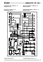
Page 25: ...AUVARIANTE CHA K FC ELECTRICAL DIAGRAM MODELS 91 151 VERSION CHA K FC DIAGRAMME ÉLECTRIQUE MODEL 91 151 VERSION CHA K FC Legenda schema elettrico a pagina 24 Schaltplan Erklärung auf Seite 24 Wiring diagram explanation on page 24 Explication de le diagramme électrique à la page 24 ...

Page 26: ...fiato valvole di intercettazione valvola di taratura giunti antivibranti ecc Avviamento e manutenzione Attenersi scrupolosamente a quanto indicato nel manuale di uso e manutenzione Tali operazioni devono comunque essere effettuate da personale qualificato INSTALLATION RECOMMENDATIONS Location Strictly allow clearances as indicated in the catalogue Ensuretherearenoobstructionsontheairsuctionanddisc...

Page 27: ...ise en place Observer scrupuleusement les espaces pour l entretien tels qu indiqués précédemment Vérifier qu il n existe aucune obstruction sur l aspiration de l air au travers de la batterie ailettée et sur le refoulement des ven tilateurs Positionner l unité de manière à n affecter qu au minimum l en vironnement émission sonore intégration sur le site etc Raccordements électriques Consulter touj...

Page 28: ...ng dienen vorbehalten Der Hersteller behält das Recht auf diese Änderungen ohne Ankündigung vor The data indicated in this manual is purely indicative The ma nufacturer reserves the right to modify the data whenever it is considered necessary Les données reportées dans la présente documentation ne sont qu indicatives Le constructeur se réserve la faculté d apporter à tout moment toutes les modific...

Reviews: