background image

30

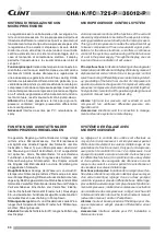
SISTEMA DI REGOLAZIONE CON

MICROPROCESSORE

La regolazione ed il controllo delle unità avvengono tra-
mite un microprocessore. Il microprocessore permette di 
introdurre direttamente i valori di set-point e i parametri di 
funzionamento. Questo tipo di microprocessore permette 
la regolazione fino a dodici compressori. Esso è dotato 
di allarme visivo, di tasti per le varie funzioni, di controllo 
continuo del sistema e di sistema di salvataggio dati in 
caso  di  mancanza  di  alimentazione  elettrica.  Il  display 
permette l'impostazione e la visualizzazione dei valori di 
set-point.

Funzioni principali:

 Indicazione temperatura aria esterna, 

di entrata e uscita acqua; identificazione e visualizzazione 
dei  blocchi  tramite  codice  alfanumerico;  regolazione  di 
una o due pompe; regolazione valvola free-cooling; ritardo 
dell'allarme pressostato differenziale alla partenza; pre-
ventilazione alla partenza; contaore di funzionamento per i 
compressori; rotazione compressori e pompe; inserimento 
non contemporaneo dei compressori; protezione antigelo; 
on-off remoto; segnalazione di funzionamento; funziona-
mento manuale; reset manuale; fermata in pump-down.

Allarmi:

 alta e bassa pressione e termico per ogni com-

pressore;  ventilatori;  antigelo;  pressostato  differenziale; 
errore configurazione.

Accessori:

  Interfaccia  seriale  per  PC;  remotazione  di-

splay.

MICROPROCESSOR CONTROL SYSTEM

A microprocessor controls all the functions of the unit and 

allows any adjustments to be made.The set-points and op-

erating parameters are set directly into the microprocessor. 

This type of microprocessor enables the adjustment of up 

to twelve compressors. It has a visual alarm signal, push-

buttons for the various functions, and offers a continuous 

control of the system as well as saving all the data in case 

of a cut in the power supply. Through the display, one can 

input and have an indication of set values.

Principal functions:

 Indication of entering and leaving water 

temperature; 

identification and display of blocks by means of 

alphanumerical code; control of one or two pumps; control 

valve free-cooling; differential pressure alarm delay at start-

up; prestarting of the fans; hour counter of compressors in 

operation; automatic changeover of compressor and pump 

sequence; compressors start individually and not together; 

frost protection; remote On-Off; operation signalling; manual 

operation; manual reset; pump down stop.

Alarms:

  high  and  low  pressure  and  overload  on  each 

compressor;  fan;  antifreeze;  differential  pressure;  con-

figuration error.

Accessories:

 Electronic card for connection to manage-

ment and service systems; remote display.

SYSTÈME DE RÉGLAGE AVEC 

MICROPROCESSEUR

Le  réglage  et  le  contrôle  des  unités  sont  effectués  au 

moyen d’un microprocesseur. Le microprocesseur permet 

d’introduire  directement  les  valeurs  d’étalonnage  et  les 

paramètres de fonctionnement. Ce type de microproces-

seur permet de contrôler d’un ou 12 compresseurs. Il est 

équipé d’une alarme sonore et visuelle, de touches pour 

les différentes fonctions, d’un contrôle continu du système 

et d’un système de sauvegarde des données en cas de 

coupure de courant. Le viseur permet de sélectionner et 

de visualiser les valeurs d’étalonnage.

Fonctions principales: 

Indication de la température d’en-

trée et de sortie de l’eau; indication des blocages au moyen 

d’un  code  numérique;  réglage  d’une  ou  deux  pompes; 

retard du régulateur pression différentielle au démarrage; 

preventilation au demarrage; compteur horaire fonctionne-

ment compresseurs; rotation des compresseurs; activation 

non simultanée des compresseurs; antigel; marche-arrêt 

à distance; indication de marche; fonctionnement manuel; 

restauration manuel; arrêt an Pump Down.

Alarmes:

 haute et basse pression et thermique pour cha-

que  compresseur;  antigel;  pression  différentielle;  erreur 

Eeprom.

Accessoires:

  Interface  sèrielle  pour  PC;  Installation  à 

distance du viseur.

FUNKTION UND AUSSTATTUNG DER

MIKROPROZESSORREGELUNGEN

Die gesamte Regelung und Kontrolle der Anlage erfolgt 
mittels  eines  Microprozessors.  Der  Mikroprozessor 
ermöglicht eine direkte Eingabe aller Sollwerte und Be-
triebsdaten. Dieser Typ von Mikroprozessor übernimmt 
die Steuerung von zwolf Verdichtern. Er ist ausgestattet 
mit optischen  Alarm, Membrantasten für verschiedene 
Funktionen, kontinuierlicher Diagnose des Systems und 
Datensicherung  bei  Stromausfall.  Das  Display  erlaubt 
die Eingabe aller Betriebsdaten und die Darstellung der 
eingegebenen Sollwerte.

Hauptfunktionen:

 Anzeige der Wasserein- und Austritt-

stemperatur; Störanzeige mittels Zifferncode; einer oder 
zwei Pumpen Regelung; Differenzdruckschalter Anlaufver-
zögerung; Belüftung bei dem Anlauf; Betriebsstundenzähler 
für den/die Verdichter; Rotation der Verdichter und Pumpen; 
Zeitverschobenes  Einschalten  der  Verdichter;  Elektro-
nischer Sicherheitsthermostat (Frostschutz); Bauseitiges 
Ein- und Auschalten; Funktionsanzeige; Manuelle Funktion; 
manuelles Reset; ausschaltung in Pump Down.

Störungsanzeigen:

 Hoch- und Niederdruck sowie Wick-

lungsschutz für jeden Verdichter; Frostschutz; Strömungs-
wächter; Störung Eeprom.

Zubehör:

 Serielle Schnittstelle für PC; mögliche Entfernung 

des Displays.

Summary of Contents for MultiPower CHA 1048-P

Page 1: ...M 208 kW TO 1102 kW GROUPES D EAU GLACÉE FREE COOLING AVEC VENTILATEURS AXIAUX ET COMPRESSEURS SCROLL DE 208 kW À 1102 kW FLÜSSIGKEITSKÜHLER FREIE KÜHLUNG MIT AXIALLÜFTERN UND SCROLL VERDICHTERN VON 208 kW BIS 1102 kW Serie Series Serie Série CHA K FC 726 P 36012 P Emissione Issue Ausgabe Edition Sostituisce Supersedes Ersetzt Remplace 02 11 Catalogo Catalogue Katalog Brochure CLB 48 7 ...

Page 2: ... ...

Page 3: ...ms explanation 31 Wiring diagrams 32 33 Installation recommendations 34 INHALTSVERZEICHNIS Seite Allgemeines 5 Bauvarianten 5 Konstruktionsmerkmale 5 Im Werk montiertes Zubehör 5 Lose mitgelieferten Zubehöre 7 Richtwerte Bedingungen am Gerätestandort 7 Einsatzbereich 7 Energieeinsparung 8 Diagramm 9 Betriebprinzip 11 Sommerbetrieb 11 Winterbetrieb 11 Mischbetrieb 11 Vorteile 11 Technische daten 14...

Page 4: ...iamento unità I compressori vengono dotati di co pertura fonoisolante PS Pompa di circolazione inserita all interno dell unità PD Doppia pompa di circolazione inserite all interno dell unità le pompe lavorano una in stand by all altra e ad ogni richiesta di accensione viene attivata per prima la pompa con meno ore di funzionamento GENERAL FEATURES Aircooled water chiller untis with axial fans comp...

Page 5: ...epompedecirculation Inséréesàl intérieurdel unité une travaille en stand by à l autre et à chaque demande d allumage la pompe avec moins d heures de fonctionnement sera activée en premier lieu ALLGEMEINE EIGENSCHAFTEN Luftgekühlte Flüssigkeitskühler mit Axiallüftern und Frei Kühlein richtung zur Energieeinsparung Zur Auswahl stehen 17 Modelle mit Kühlleistungen von 208 bis 1102 kW Die CHA K FC Ger...

Page 6: ...eratura acqua in uscita C 4 18 Outlet water temperature Salto termico acqua 1 C 3 9 Water thermal difference 1 Temperatura aria esterna C 20 46 Ambient air temperature Max pressione di esercizio lato acqua scambiatore kPa 1000 Max operating pressure heat exchanger water side CONDIZIONI DI RIFERIMENTO I dati tecnici indicati a pagina 12 e 13 si riferiscono alle seguenti condizioni di funzionamento ...

Page 7: ...it 30 Ethy lenglycol Kaltwassereintrittstemperatur 15 C Kaltwasseraustrittstemperatur 10 C Lufteintrittstemperatur am Verflüssigerregister 35 C schalldruckpegel DIN 45635 messungineinemMeterAbstandgegenüberderVerflussigerseite in einer Höhe von 1 5 m Gemab DIN 45635 schalldruckpegel ISO 3744 Mittlerer Schalldruck in 1 m von der Einheit in freien Feld wie von ISO 3744 angegeben Separate Einspeisung...

Page 8: ...re il risparmio energeticoattraversoleprestazionidelchillerfree coolingconfrontate con le prestazioni di un normale chiller Grafico A La curva n 1 è riferita al funzionamento di un normale chiller e mostra la potenza assorbita alle diverse condizioni di temperatura ambiente La curva n 2 è riferita agli assorbimenti elettrici di un chiller free coolingallediversecondizioniditemperaturaambienteedèsu...

Page 9: ... 6 8 10 12 14 16 18 20 22 24 26 28 30 32 0 1 00 200 300 400 500 600 700 14 12 10 8 6 4 2 0 2 4 6 8 10 12 14 16 18 20 22 24 26 28 30 32 2 1 a b c 0 5000 10000 15000 20000 25000 30000 35000 14 12 10 8 6 4 2 0 2 4 6 8 10 12 14 16 18 20 22 24 26 28 30 32 ...

Page 10: ...e di funzionamento Minori spese di manutenzione OPERATING PRINCIPLE The Free Cooling series of refrigerating units are designed to cool a gly col water solution Besides the main components used on ordinary chillers such as com pressors condensers evaporator expansion valves these units also include a free cooling water coil A control system consisting of a 3 way modulating valve and a set of probe...

Page 11: ... Moins de frais de maintenance BEZEICHNUNG DESCRIPTION BEZEICHNUNG DESCRIPTION CA Luftgek Verflüssiger Condenseur SB Mikroprocessor Microprocesseur CAF Free Cooling Wärmetauscher Condenseur avec Free Cooling ST1 Temperaturfühler Sonde de travail EW Verdampfer Voyant liquide ST2 Frostschutzfühler Sonde anti gel MC Verdichter Compresseur ST3 Temperaturfühler Wassereintritt Sonde de l eau en entrée M...

Page 12: ...1 4x20 5 2x26 0 6x25 6 8x20 2 4x20 9 4x26 1 8x26 0 10x22 2 10x25 9 Carica olio unitaria Kg 3 3 3 3 3 3 3 6 3 6 3 3 3 3 3 6 3 6 3 3 3 6 Versione standard e con accessorio SL Portata aria m s 21 1 21 1 27 2 26 1 36 1 36 1 32 8 32 8 42 2 Ventilatori n 4 4 6 6 8 8 8 8 10 Potenza nominale ventilatori kW 7 0 7 0 10 5 10 5 14 0 14 0 14 0 14 0 17 5 Corrente nominale ventilatori A 15 15 22 22 30 30 30 30 3...

Page 13: ...3 6x26 0 12x35 2 6x34 6 6x45 9 12x45 6 6x44 8 6x51 3 12x52 6 Unitary absorbed current 1 3 3 3 6 3 6 6 7 6 7 6 7 6 7 6 7 7 2 7 2 Oil charge Standard version and with SL accessory 42 2 42 2 45 6 50 6 61 7 67 8 76 1 76 1 Airflow 10 10 10 12 14 16 18 18 Fans 17 5 17 5 17 5 21 0 24 5 28 0 31 5 31 5 Nominal power fans 37 37 37 45 52 60 67 67 Nominal current fans 84 84 87 88 88 89 89 90 Sound pressure le...

Page 14: ... 1 4x20 5 2x26 0 6x25 6 8x20 2 4x20 9 4x26 1 8x26 0 10x22 2 10x25 9 Ölmenge pro Einheit Kg 3 3 3 3 3 3 3 6 3 6 3 3 3 3 3 6 3 6 3 3 3 6 Standard Version und mit Zubehör SL Nennluftmenge m s 21 1 21 1 27 2 26 1 36 1 36 1 32 8 32 8 42 2 Radiallüftern n 4 4 6 6 8 8 8 8 10 Lüftern Nennleistung kW 7 0 7 0 10 5 10 5 14 0 14 0 14 0 14 0 17 5 Lüftern Nennstrom A 15 15 22 22 30 30 30 30 37 Schalldruckpegel ...

Page 15: ...2 6x34 6 6x45 9 12x45 6 6x44 8 6x51 3 12x52 6 Courant absorbée unitaire 1 3 3 3 6 3 6 6 7 6 7 6 7 6 7 6 7 7 2 7 2 Charge huile unitaire Version standard et avec accessoire SL 42 2 42 2 45 6 50 6 61 7 67 8 76 1 76 1 Débit d air 10 10 10 12 14 16 18 18 Ventilateurs 17 5 17 5 17 5 21 0 24 5 28 0 31 5 31 5 Puissance nominal ventilateurs 37 37 37 45 52 60 67 67 Courant nominale ventilateurs 84 84 87 88...

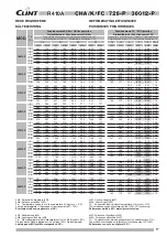
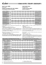
Page 16: ...352 123 375 112 396 102 417 92 7 11 378 123 402 112 425 102 446 92 9 13 405 123 431 113 455 103 477 93 0 15 434 124 461 113 486 103 510 93 2 1208 P 5 334 131 356 119 377 108 397 97 9 7 360 132 382 120 404 108 426 97 9 9 387 132 411 120 434 108 457 98 2 11 415 132 440 120 465 109 489 98 5 13 446 133 472 121 497 109 523 98 9 15 477 133 505 121 532 109 558 99 2 13010 P 5 368 146 394 133 418 122 440 1...

Page 17: ...24012 P 5 615 265 659 240 701 217 741 197 7 662 265 709 240 753 218 796 198 9 712 266 762 240 809 218 854 198 11 765 266 817 241 867 218 914 199 13 820 266 876 241 928 219 979 200 15 878 267 937 241 993 220 1046 202 27012 P 5 690 304 738 276 783 252 826 230 7 742 304 794 276 842 252 887 230 9 798 304 853 277 903 252 951 231 11 857 305 915 277 968 253 1019 231 13 919 305 980 277 1037 253 1090 232 1...

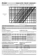
Page 18: ...cted with the correction factors shown above 30 40 50 60 70 80 20 25 10 8 7 5 12 14 16 18 7 2 6 P 7 8 6 P 8 2 6 P 9 0 6 P 1 0 4 8 P 1 1 2 8 P 1 2 0 8 P 1 3 0 1 0 P 1 5 0 1 0 P 1 6 8 1 2 P 1 8 0 1 2 P 1 8 0 1 2 P 1 8 0 1 2 P 2 1 0 1 2 P 2 1 0 1 2 P 2 1 0 1 2 P 2 4 0 1 2 P 2 4 0 1 2 P 2 4 0 1 2 P 2 7 0 1 2 P 2 7 0 1 2 P 2 7 0 1 2 P 3 0 0 1 2 P 3 0 0 1 2 P 3 0 0 1 2 P 3 3 0 1 2 P 3 3 0 1 2 P 3 3 0 1 ...

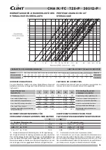
Page 19: ... 10 4 m C W 0 96 0 99 0 88 x 10 4 m C W 1 76 x 10 4 m C W 0 93 0 98 1 76 x 10 4 m C W Glykol Prozent pro Gewicht 0 10 20 30 40 50 Pourcentage de glycole ethylènique en poids Gefriertemperatur C 0 4 5 9 5 15 5 21 5 32 5 Température de congélation C Korr koeff Kälteleistung 1 075 1 048 1 021 1 0 978 0 946 Coeff corr puissance frigorifique Korr koeff Leistungsaufnahme 1 01 1 006 1 002 1 0 998 0 995 C...

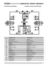
Page 20: ...o bassa pressione accessorio Low pressure guage accessory MV Ventilatori assiali Axial fans RC Resistenza carter Crank case heater SF Indicatore di liquido Sight glass SPH Pressostato di alta pressione High pressure switch SPL Pressostato di bassa pressione Low pressure switch SPS Pressostato di sicurezza 1048 P 36012 P Safety pressure gauges 1048 P 36012 P TP Trasduttore di pressione Pressure tra...

Page 21: ... Manomètre de basse pression accessoire MV Axiallüftern Ventilateurs axiaux RC Öflsumpfheizung Résistence carter SF Schauglas Indicateur de liquide SPH Hochdruckwächter Pressostat de haute pression SPL Unterdruckwächter Pressostat de basse pression SPS Sicherheitsdruckschalter 1048 P 36012 P Safety pressure gauges 1048 P 36012 P TP Druckgeber Transducteur de press VDS Sicherheitsventil Vanne secur...

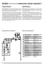
Page 22: ...e Single circulating pump MV Ventilatori assiali Axial fans P Pressostato differenziale acqua Differential water pressure switch RCF Valvola a 3 vie 3 way valve RP Rubinetto Intercepting valve SCA Scarico acqua Water drain SFA Sfiato aria Air vent ST1 Sonda di lavoro Sensor for unit operation ST2 Sonda antigelo Antifreeze sensor ST3 Sonda aria esterna Outside air probe ST4 Sonda ingresso acqua Wat...

Page 23: ...nge d eau PS Circuithydrauliqueavecpompedecirculationcomprend échangeur air eau vanne à 3 voies évaporateur sonde travail sonde anti gel sonde de l eau en entrée sonde de l air extérieur pressostat différentiel côte eau pompe vase d expansion sou pape de securité et relay thermique PD Circuit hydraulique avec double pompe de circulation comprend échangeur air eau vanne à 3 voies évaporateur sonde ...

Page 24: ...i idraulici Zuzüglich Betriebsgewicht und Wasseranschlüsse der Geräte Additional weight in operation and water connections Poids supplémentaire en fonctionnement et raccords hydrauliques MODELLI MODELLE 726 P 786 P 826 P 906 P 1048 P 1128 P 1208 P 13010 P 15010 P MODELS H2O Magg peso in funzionamento Betriebsgewicht zzgl Kg 13 15 16 18 19 23 23 26 29 H2O Additional weight while funct Suppl de poid...

Page 25: ...atteristiche delle pompe EINHEIT MIT BEHÄLTER UND PUMPEN Pumpenkennlinien UNITS WITH PUMPS Characteristic pump curves UNITES AVEC POMPES Courbes caractéristiques Mod CHA K FC 1208 P CHA K FC 13010 P CHA K FC 15010 P Mod CHA K FC 36012 P Mod CHA K FC 786 P CHA K FC 826 P CHA K FC 906 P CHA K FC 1048 P CHA K FC 1128 P Mod CHA K FC 16812 P CHA K FC 18012 P CHA K FC 21012 P Mod CHA K FC 24012 P CHA K ...

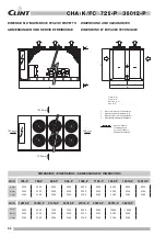
Page 26: ...0 2360 2360 2360 2360 2360 2360 2360 2360 MOD 16812 P 18012 P 21012 P 24012 P 27012 P 30012 P 33012 P 36012 P A mm 6200 6200 7200 7200 8400 9600 10600 10600 B mm 2200 2200 2200 2200 2200 2200 2200 2200 C mm 2360 2360 2360 2360 2360 2360 2360 2360 Spazi di rispetto Clearance area Service Freiräume Espces Techniques Y Connessioni idrauliche unità standard Y Water connections for standard units Y Was...

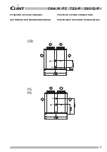
Page 27: ...1500 1000 1000 1000 1000 1000 1000 1000 1000 1000 1000 330 330 330 330 330 2200 2200 2200 2200 2200 2200 2200 2200 2200 2200 Posizione attacchi idraulici Anordnung der Wasseranschlüsse Position of water connections Position des raccords hydrauliques ...

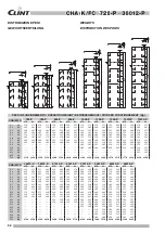
Page 28: ...410 415 410 415 K8 Kg 265 265 265 265 290 290 305 305 320 325 325 330 355 360 390 400 400 405 K9 Kg 290 295 295 300 320 325 350 355 370 375 K10 Kg 260 260 260 260 280 280 320 320 340 345 K11 Kg 320 325 K12 Kg 285 285 K20 Kg Tot Kg 2310 2340 2320 2350 2500 2530 2630 2660 3190 3230 3220 3260 3470 3510 3770 3820 4250 4300 CHA K FC 16812 P 18012 P 21012 P 24012 P 27012 P 30012 P 33012 P 36012 P STD SL...

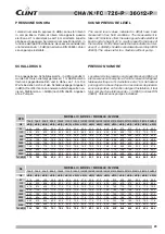
Page 29: ...A dB A dB A dB A dB A dB A dB A dB A dB A dB A dB A 63 49 0 49 5 50 0 50 5 51 0 52 5 52 5 52 5 53 0 53 5 54 0 55 5 57 0 57 0 57 5 57 5 58 0 125 60 5 61 0 62 0 62 5 62 5 64 0 64 0 64 0 65 0 65 5 65 0 68 0 69 5 70 0 70 0 70 5 72 0 250 70 5 70 0 72 5 73 5 73 5 74 5 75 0 74 5 76 5 77 0 76 0 79 0 80 5 80 5 80 5 81 0 82 5 500 71 5 72 5 73 0 74 0 75 0 76 0 76 0 75 5 77 0 77 5 78 5 80 5 82 0 82 5 83 0 83 ...

Page 30: ...tifreeze differential pressure con figuration error Accessories Electronic card for connection to manage ment and service systems remote display SYSTÈME DE RÉGLAGE AVEC MICROPROCESSEUR Le réglage et le contrôle des unités sont effectués au moyen d un microprocesseur Le microprocesseur permet d introduire directement les valeurs d étalonnage et les paramètres de fonctionnement Ce type de microproce...

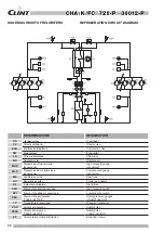
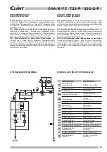
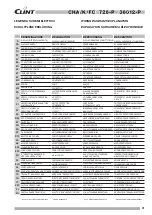
Page 31: ...RE EVAPORATOR HEATER VERDAMPFER ELEKTROHEIZUNG RESISTANCE EVAPORATEUR RF RELÈ DI FASE PHASE SEQUENCE RELAY PHASENRELAIS RELAIS SEQUENCE PHASE RG REGOLATORE DI GIRI SPEED GOVERNOR DREHZALREGLER REGULATEUR VITESSE RQ RES QUADRO ELETTRICO ELECTRICAL BOARD HEATER SCHALTSCHRANK ELEKTROHEIZUNG RESISTANCE CADRE ELECTRIQUE RT PIPES HEATER LEITUNGEN BEGLEITHEIZUNG RESISTENZA TUBI RESISTENCE TUYAUX RTP RELÈ...

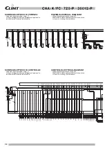
Page 32: ...ines indicate optional electrical connections or to carry out during the installation CONTROL ELECTRICAL DIAGRAM Wiring diagram explanation at page 31 Dotted lines indicate optional electrical connections or to carry out during the installation RG1 MV1 KV1 RTV7 RTV2 RTV1 L2 L1 PE L3 L2 L1 L3 PE MV2 L3 L2 L1 PE MV3 L1L2 MV4 RTV3 MV6 L1 L3 PE RTV4 MV5 L2L3 PE RTV5 RTV6 L2L3 PE L1 L3 PE L1L2 MV7 PE P...

Page 33: ...RTV10 RTV9 RTV12 RTV11 RTV15 RTV17 RTV14 RTV16 RTV18 RTV13 110A 109A 108A 107A 106A 105A 104A 103A 104B 103B KA2 KA2 KA2 KA3 KA3 KA3 KA4 KA4 KA4 KA5 KA5 KA5 SBP2 SBP1 97 98 99 100 102 101 PI12 REGELUNG SCHALTPLAN Schaltplan Erklärung auf seite 31 Die ausgezeichneten Sektionen sind die optionalen oder bei der Installation durchzuführenden Verbindungen SCHÉMA ÉLECTRIQUE DE CONTRÔLE Explanation de le...

Page 34: ...lvole di intercettazione valvola di taratura giunti antivibranti ecc Avviamento e manutenzione Attenersi scrupolosamente a quanto indicato nel manuale di uso e manutenzione Tali operazioni devono comunque essere effettuate da personale qualificato INSTALLATION RECOMMENDATIONS Location Strictly allow clearances as indicated in the catalogue Ensuretherearenoobstructionsontheairsuctionanddischarge si...

Page 35: ...ilibrage jonctions antivibratiles etc Mise en service et entretien Se tenir scrupuleusement à ce qui est indiqué dans le manuel d utilisation et d entretien Ces opérations seront toutefois effec tuées par du personnel qualifié HINWEISE ZUR INSTALLATION Aufstellung Für ausreichende Be und Entlüftung des Gerätes sorgen Die Aufstellung des Gerätes ist so vorzunehmen das es allseitig erreichbar ist Es...

Page 36: ...rung dienen vorbehalten Der Hersteller behält das Recht auf diese Änderungen ohne Ankündigung vor The data indicated in this manual is purely indicative The ma nufacturer reserves the right to modify the data whenever it is considered necessary Les données reportées dans la présente documentation ne sont qu indicatives Le constructeur se réserve la faculté d apporter à tout moment toutes les modif...

Reviews: