INSTALLATION
A. MOTOR INSTALLATION
1. Remove the handwheel from the machine.
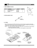
2. Remove the four screws that hold the bearing housing to the machine, see ML970-15. Attach
the sewing head mounting plate, 02-4108-01 to the machine with the screws provided
30-1210-01.
3. Attach the sewing head coupling assembly 10-1544-01 to the machine removing all play from
the main shaft.
4. Rotate the machine in the standard direction of rotation until the point of the needle is even with
the top of the throat plate.
5. With power to the system and the motor detached from the machine press the "arrow right" and
"SBT" buttons simultaneously. The display will read "TEST SYSTEM" briefly the "PRESS
SET".
6. Press the "SET" button twice, the display will read "TEST INDEX" briefly then show a broken
line (---------) rotate the motor slowly by hand until the display reads (---INDEX---).
7. Align the motor coupling with the sewing head coupling, keeping the motor in the INDEX posi
tion, and attach the motor to the machine.
Note: The sewing head may have to be rotated slightly in order to align the couplings but
the INDEX signal must be between the needle up and the needle down positions.
B. LCD DISPLAY
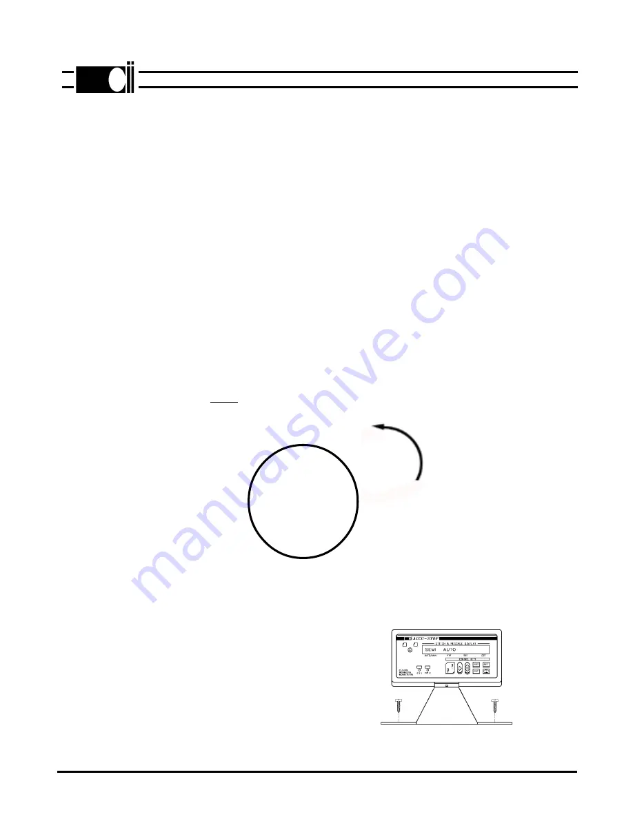
Mount the LCD display console at
a convenient location on the table top
as shown in figure 2-2.
SECTION II
®
ML970-6
2-1
Fig. 2-2
NEEDLE UP
NEEDLE DOWN
TRIM
INDEX
DIRECTION OF
ROTATION
Fig. 2-1


