C. SWITCH BOX
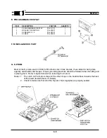
Install switch box at a convenient
location under the table. See fig. 2-3.
D. POWER AND CABLE CONNECTIONS
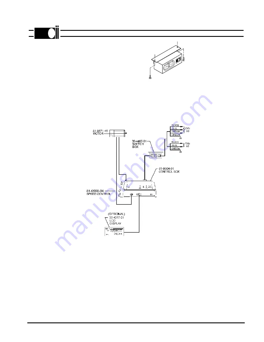
Refer to figure 2-4 and connect all cables as shown. The system can be operated from 230V, 3
phase or 230V, single phase power.
2-2
E. MOTOR ROTATION
Before attaching the motor to the sewing head, turn power on, then move the pedal forward and
note the direction of motor pulley rotation. If incorrect, do the following:
1. Turn power off.
2. Refer to section III-B, Hidden Parameters, and follow the instructions to change motor rotation.
The parameter is in the "**** Toggle Switches" group.
3. Install the motor.
FIG. 2-4
®
ML970-7
Fig. 2-3
CABLE DIAGRAM


