background image

3-3

®

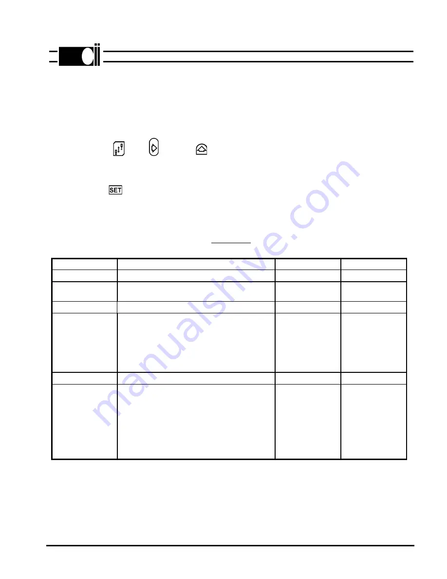
C. MASTER RESET

In some cases it may be necessary to reset all parameters to their default values.  This is done as
follows:

1. Turn power off, if it is on, then wait until the display goes blank.

2. Press the          key,         key and         key simultaneously.  Keep pressed then,

3. Turn power on.  The display alternates between "Push Set" and "For Reset".

4. Push the         key within 10 cycles.

5. The word "Programming" is displayed.  The parameters will be reset to their default values after

a few seconds.

TABLE 3-2

ML970-10

PARAMETER

DESCRIPTION

DEFAULT

RANGE

****SPEED GROUP

RPM

RPM

TRIM/POS

MAXIMUM

Sets the positioning speed of the machine

Sets the maximum speed of the machine

220

4200

100-250

500-9900

****MISCELLANEOUS

POS. DOWN

POS. UP

TRIM COUNT

PF DUTY

REVERSE COUNT

Sets the Needle Down position.*

Sets the Needle Up position.*

Sets when the trimmer activates.*

Average voltage applied to the presser foot

solenoid.

Sets the amount the machine will turn back

if the reverse mode is activated.

130

210

140

5

3

0-255

0-255

0-255

1-10

0-255

****TOGGLE SWITCHES

DIRECTION

TRIM

REVERSE MODE

Sets the motor direction.

++CW = Clockwise

--CCW = Counterclockwise.

2 Position = The machine will not stop when

the trimmer is activated.

3 Position = The machine stops when the

trimmer is activated.

Turns the reverse function On or Off.

--CCW

2 POS.

DISABLED

++CW / --CCW

2 POS. / 3 POS.

ENABLED /

DISABLED

* See Section II, Teach-in mode.

Summary of Contents for 970

Page 1: ...CLINTON MODEL 970 VARIABLE SPEED DC SERVO MOTOR SERVICE MANUAL ML970 3 NEEDLE POSITIONER THREAD TRIMMER 40 0258 01 ...

Page 2: ... DISPLAY 3 1 A B C DIRECT ACCESS PARAMETERS HIDDEN PARAMETERS MASTER RESET 3 1 3 2 3 3 SECTION IV TEST PROGRAM 4 1 1 TREADLE TEST 2 INDEX SIGNAL 3 ENCODER TEST 4 MOTOR BALANCE TEST 4 1 4 1 4 1 4 1 SECTION V CONNECTOR DIAGRAMS 5 1 SECTION VI DRAWINGS AND PARTS LIST 6 1 A B C D E F G MAJOR ASSEMBLIES MOTOR MOUNTING ASSEMBLY CONTROL BOX ASSEMBLY POWER SUPPLY PROGRAMMABLE DISPLAY MISCELLANEOUS PARTS E...

Page 3: ...omponents interact to give a fast accurate and reliable sewing machine drive The components of the system are shown in figure below The model 970 has outputs for a trimmer footlift wiper and needle cooler It can be used to operate all Clinton trimmers as well as the Singer Union Special Pfaff Juki and Brother undertrimmers and chain stitch machines The programmable LCD display is used to select th...

Page 4: ...ess the arrow right and SBT buttons simultaneously The display will read TEST SYSTEM briefly the PRESS SET 6 Press the SET button twice the display will read TEST INDEX briefly then show a broken line rotate the motor slowly by hand until the display reads INDEX 7 Align the motor coupling with the sewing head coupling keeping the motor in the INDEX posi tion and attach the motor to the machine Not...

Page 5: ...single phase power 2 2 E MOTOR ROTATION Before attaching the motor to the sewing head turn power on then move the pedal forward and note the direction of motor pulley rotation If incorrect do the following 1 Turn power off 2 Refer to section III B Hidden Parameters and follow the instructions to change motor rotation The parameter is in the Toggle Switches group 3 Install the motor FIG 2 4 ML970 7...

Page 6: ...up of the hidden parameters then select the NEEDLEup parameter Rotate the handwheel of the machine until the take up lever is in dead center position Press the treadle forward the machine will make one revolution then save the needle up position 3 TRIM To set the trim position access the MISC group of the hidden parameters then select the TRIMcnt parameter Rotate the handwheel of the machine until...

Page 7: ...four 4 groups They are 1 SPEEDS 2 TIMERS 3 COUNTERS and 4 TOGGLE SWITCHES Table 3 1 describes each parameter shows the default value and range of adjustment for each parameter 3 1 SECTION III ML970 8 To change a parameter follow the sequence described below 1 Press the key to enter the programming mode Continue pressing this key until the para meter group that is to be changed is displayed As an a...

Page 8: ...4 stars as described in section A above PARAMETER DESCRIPTION DEFAULT RANGE SPEED GROUP RPM RPM SOFTSTRT Sets the RPM of the machine while in the soft start option 500 140 2000 TIMER GROUP MS MS START DEL TRIM TIME WIPER TIME Delays machine start to allow presser foot to drop Sets the amount of time that the trimmer is on Sets the amount of time that the wiper is on 80 90 80 10 500 50 250 10 250 C...

Page 9: ...itioning speed of the machine Sets the maximum speed of the machine 220 4200 100 250 500 9900 MISCELLANEOUS POS DOWN POS UP TRIM COUNT PF DUTY REVERSE COUNT Sets the Needle Down position Sets the Needle Up position Sets when the trimmer activates Average voltage applied to the presser foot solenoid Sets the amount the machine will turn back if the reverse mode is activated 130 210 140 5 3 0 255 0 ...

Page 10: ...ay shows INDEX signal If this signal is not displayed within one revolution of the handwheel the encoder has failed 3 Encoder Test CAUTION Separate the coupling The coupling must be separated because the motor may not develop sufficient torque to turn the machine Press the button The display will read TEST ENCODER briefly then PUSH START enc Press the button the motor will begin to rotate slowly a...

Page 11: ...NCTION 1 NOT USED NOT USED 2 6 AUX INPUTS 1 2 3 4 5 6 5 GND CHASSIS GND I 1 I 2 I 3 3 4 AUX OUTPUTS 1 2 3 4 48 V R1 48 V R2 4 2 FOOTLIFT 1 2 FOOTLIFT SOL 48V 5 9 TRIM WIPER BACKTACK SOLENOIDS AND MANUAL BACKTACK SW 1 4 2 5 3 6 7 8 9 WIPER SOL WIPER SOL 48V TRIMMER SOL TRIMMER SOL 48V BACKTACK SOL BACKTACK SOL 48V MANUAL BACK TACK SWITCH NOT USED ...

Page 12: ...1 ENCODER S2 SIG GND PHASE C PHASE B PHASE A INDEX 7 16 LCD DISPLAY 1 2 3 4 5 6 7 8 9 10 11 12 13 14 15 16 EXT1 CHASSIS GND 5V GND D0 D1 D2 D3 D4 D5 D6 D7 CA1 E ERD CA0 8 4 AC POWER 220V 3 1 2 3 4 PHASE A PHASE B PHASE C CHASSIS GND 9 4 MOTOR VOLTAGE 1 2 3 4 PHASE A PHASE B PHASE C CHASSIS GND ...

Page 13: ...DRAWINGS AND PARTS LIST MODEL 970 6 1 SECTION VI ML970 14 A MAJOR ASSEMBLIES 30 4400 01 SWITCH BOX 81 0904 01 CONTROL BOX 81 0871 45 MINI TAURUS 30 4317 01 LCD DISPLAY ...

Page 14: ......

Page 15: ......

Page 16: ......

Page 17: ...d in Clinton s Mini Taurus are Cmos devices thus subject to being dam aged by electrostatic discharges Proper grounding practices should be followed when handling and replacing them Refer to figure below when replacing the E prom Notes 1 The notch on the E prom chip and the other chips on the board all face towards the back of the board towards back of chassis 2 Check to make sure that all of the ...

Reviews: