M03I40M7-03 15/11/07
page
44
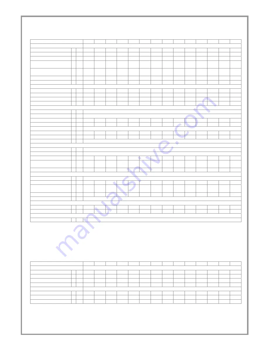
Acoustic configuration: Standard (ST)/Extremely low noise(EN) / Energy efficiency: Efficiency class B
Size
2.160 2.180 2.220 2.250 2.280 2.300 2.320 2.340 2.360 2.420 2.450 2.480 2.540 2.600
COOLING
Cooling
capacity
1
kW 408 455 562 620 698 773 828 903 952 993 1049
1171 1295 1458
Compressor power input
kW 86 96.5 118 130 147 162 177 187 196 208 223 246 271 308
Total power input
kW 87 97.5 119 131 148 163 178 188 197 209 224 247 272 309
Heating capacity total
recovery
2 kW 473 528 649 718 809 894 962 1039 1095 1148 1217 1358 1503 1692
Heating capacity partial
recovery
2
kW
74.2 82.7 102 112 127 140 151 163 172 180 191 212 235 265
EER
4.69 4.67 4.73 4.72 4.71 4.73 4.66 4.8 4.82 4.74 4.68 4.74 4.75 4.72
ESEER
5.28 5.26 5.33 5.32 5.3 5.33 5.25 5.41 5.43 5.34 5.27 5.34 5.35 5.32
HEATING
Heat
output
3 kW 473 528 649 718 809 894 962 1039 1095 1148 1217 1358 1503 1692
Compressor power input
kW 107 119 146 161 184 201 218 231 243 258 275 303 337 381
Total power input
kW 108 120 147 162 185 202 219 232 244 259 276 304 338 382
COP
4.4 4.4 4.42 4.44 4.37 4.42 4.39 4.48 4.48 4.43 4.41 4.47 4.44 4.43
COMPRESSOR
Type of compressors
4
SCREW
No. of Compressors
Nr
2
Rated
power
(C1)
HP 80 90 110 125 140 140 160 160 180 210 210 240 270 300
Nominal
Power
(C2)
HP 80 90 110 125 140 160 160 180 180 210 240 240 270 300
Std Capacity control steps Nr
STEPLESS
Oil
charge
(C1)
l 11 11 22 19 19 19 35 35 35 35 35 25 25 25
Oil
charge
(C2)
l 11 11 22 19 19 35 35 35 35 35 35 25 25 25
Refrigerant circuits
Nr
2
INTERNAL EXCHANGER
Type of internal exchanger 5
S&T
No. of internal exchangers Nr 1
Water flow rate
l/s 19.5 21.7 26.8 29.6 33.3 36.9 39.6 43.1 45.5 47.4 50.1 55.9 61.9 69.7
internal exchanger
pressure drop
kPa 61 56.2 51.4 61.1 75.2 66.9 58.9 39.9 43.8 78.6 52.2 66.3 79.3 70.9
Water content
l 164.4 159.3 263.3 263.3 263.3 248.3 241.2 409.6 409.6 418.6 409.6 400.9 400.9 461.8
EXTERNAL EXCHANGER
type of external exchanger 6
S&T
Water flow rate
l/s 23.6 26.4 32.5 35.8 40.4 44.7 48 52.1 54.9 57.4 60.8 67.7 74.8 84.4
external exchanger
pressure drop
kPa 31.7 29.7 34.5 33.4 34.8 33.4 30.5 33 34 36.9 36.3 35.9 34.9 30.9
Water content
l 38 43 49 54 59 67 75 75 75 80 85 95 101 131
Quantity
Nr 2
CONNECTIONS
Water
fittings
7
5" 5" 6" 6" 6" 6" 6" 8" 8" 8" 8" 8" 8" 8"
Water
fittings
7
5" 5" 5" 5" 5" 5" 5" 5" 5" 5" 5" 5" 5" 6"
POWER SUPPLY
Standard power supply
V 400/3/50
(1) data referred to the following conditions :
internal exchanger water = 12/7°C
external exchanger water = 30/35°C
(2) recovery exchanger water=40/45°C
(3) data referred to the following conditions :
external exchanger water = 40/45°C
internal exchanger water = 12/7°C
(4) DSW = twin-screw compressor
(5) S&T = tube bundle
(6) S&T = tube bundle
(7) Fittings with flexible joint and solder pipe connection
OPERATING LIMITS (COOLING)
Size
2.160 2.180 2.220 2.250 2.280 2.300 2.320 2.340 2.360 2.420 2.450 2.480 2.540 2.600
EXTERNAL EXCHANGER
Max water inlet temperature
1
°C
51 51 51 51 51 51 51 51 51 51 51 51 51 51
Max water inlet temperature
2 °C
55 55 55 55 55 55 55 55 55 55 55 55 55 55
Max water inlet temperature
3 °C
62 62 62 62 62 62 62 62 62 62 62 62 62 62
Min. water outlet temperature
1
°C
26 26 26 26 26 26 26 26 26 26 26 26 26 26
INTERNAL EXCHANGER
Max water inlet temperature
°C 20.5 20.5 20.5 20.5 20.5 20.5 20.5 20.5 20.5 20.5 20.5 20.5 20.5 20.5
Min. water outlet temperature
4
°C
5 5 5 5 5 5 5 5 5 5 5 5 5 5
Min. water outlet temperature
5
°C
-8 -8 -8 -8 -8 -8 -8 -8 -8 -8 -8 -8 -8 -8
(1) unit at full load: internal exchanger water 12/7°C
(2) capacity-controlled unit (automatic capacity control)
(3) unit not operating
(4) Standard Version
(5) Low temperature version
Fluid with ethylene glycol of 40%


