M62P40B5-02 21/09/07
pag
40
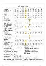
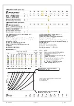
TECHNICAL DATA
SIZE
82
102
122
142
162
182
202
222
242
282
COOLING
Cooling
capacity
1 kW 22,2 25,6 29 34 38,2 41,4 48,2 54,9 58,2 68
Compressor
power
input
1 kW 7,7 9,3 10,9 12,5 14,8 16,7 18,1 21,2 23,2 26,2
Total
power
input
2 kW 8,4 10 11,5 13,9 16,1 17,9 19,5 22,5 24,5 28,8
EER
3
2,64 2,56 2,52 2,44 2,37 2,31 2,47 2,44 2,37 2,36
EER
4
4,96 5,02 5,01 4,22 4,61 4,6 4,5 4,69 4,75 4,3
EER
5
3,95 3,85 4,01 3,44 3,55 3,7 3,66 3,66 3,6 3,6
HEATING
Heat
output
6 kW 26 30,4 34,7 40,3 45,4 49 57,7 65,5 69,7 80
Compressor power input
kW
7,7
9
10,4
12,2
14
15,3
18,3
20,9
22,5
26,1
Total
power
input
2 kW 8,4 9,6 11 13,6 15,3 16,6 19,7 22,2 23,9 28,8
COP
3,1 3,16 3,15 2,96 2,96 2,95 2,92 2,95 2,91 2,77
COMPRESSOR
Type of compressors
SCROLL
No. of Compressors
Nr
2
Std Capacity control steps
Nr
3
Refrigerant charge
Nr
1
Refrigerant
circuits
(C1)
7 kg 12 12 12 15 15 15 20 20 20 22
INTERNAL EXCHANGER
Type of internal exchanger
8
PHE
No. of internal exchangers
Nr
1
Water
flow
rate
l/s 1,1 1,2 1,4 1,6 1,8 2 2,3 2,6 2,8 3,3
Useful
pump
discharge
head
kPa
148 140 135 190 187 185 175 169 160 103
Water
content
7 l 1,7 2 2,4 2,6 3,1 3,4 3,8 4,4 4,4 5,5
EXTERNAL EXCHANGER
Quantity
Nr
2
EXTERNAL SECTION FANS
Type of fans
9
AX
Number
of
fans
Nr 2 2 2 4 4 4 6 6 6 6
Standard
air
flow
l/s 3056 3056 3056 4125 4125 4125 6120 6120 6120 7800
Installed
unit
power
kW 0,22 0,22 0,22 0,15 0,15 0,15 0,15 0,15 0,15 0,19
HYDRAULIC CIRCUIT
Max water side pressure
kPa
550
Safety valve calibration
kPa
600
EXPANSION VESSEL
Expansion vessel capacity
l
5
No. of expansion vessels
Nr
1
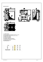
DIMENSIONS
Length
mm 1560 1560 1560 1595 1595 1595 2130 2130 2130 2160
Depth
mm 678 678 678 1107 1107 1107 1107 1107 1107 1107
Height
mm 1367 1367 1367 1570 1570 1570 1570 1570 1570 1570
STANDARD UNIT WEIGHTS
Shipping
weight
kg 310 315 320 440 470 490 560 580 600 660
Operating
weight
kg 330 335 340 460 490 510 580 600 620 670
(1) data referred to the following conditions :
internal exchanger water = 12/7°C
ambient temperature = 35°C
(2) The total input is given by the compressor input + fans power
input + pump power input -
proportional part of the water pump to supply the available head
to installation input
(3) 100% EER
internal exchanger water supply temperature = 7°C
outside air temperature 35°C
(4) 66% EER
internal exchanger water supply temperature = 10°C
ambient temperature = 28°C
(5) 33% EER
internal exchanger water supply temperature = 13°C
ambient temperature = 25°C
(6) data referred to the following conditions :
ambient temperature = 7°C (RH = 85%)
external exchanger water supply temperature 45°C
(7) approximate values
(8) PHE = plates
(9) AX = axial-flow fan
CUT-OUT AND CONTROL SETTINGS
Opens
Closes
High pressure switch
(kPa)
2750
2000
Low pressure switch
(kPa)
230
360
Max compressor starts/hour
(n°)
10
Antifreeze protection
(°C)
4
5,5
Safety discharge thermostat
(°C) 120
Note:
The safety "high pressure switch" and "safety discharge thermostat" must be reset manually from the control unit. The "low pressure switch"
resets automatically. In some units the safety discharge thermostat is internal to the compressor.


