M0G940E8-00 04/07/08
pag
5
INSTRUCTIONS FOR THE USER
•
This is a partial sintex of the information provided in the manual; carefully read this manual
•
Carefully read this manual. Keep it with the electrical diagram. Make it available to technicians for servicing.
•
Ask the installer for training on start-up, shutdown, changing set points, placing in at-rest status, maintenance, what to do
or not to do in the event of a breakdown.
•
Provide for scheduled maintenance by specialized technicians so as to ensure long-lasting operation of the unit.
•
If you expect the machine to be shut down for long periods of time, disconnect the electrical power supply. In winter, take
necessary measures to deal with possible freezing (unit and system pipes) .
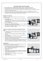
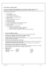
PRINCIPLE OF OPERATION
SUMMER: the cooling cycle allows the transfer of excess indoor heat to the
external environment.
1. The compressor compresses the refrigerant gas, placing it at high pressure
and high temperature.
2. In the external coil, the refrigerant is cooled, and the heat is released into the
environment by means of the fan. This is why the coil needs to be kept clean
and free of obstacles.
3. When it cools, the refrigerant becomes liquid.
4. The expansion valve causes a sudden drop in the pressure of the refrigerant,
which becomes very cold as its volume increases.
5. In the exchanger, the refrigerant evaporates and absorbs the heat from the
water that returns to the system, cooling it.
2
1
3
4
5
6
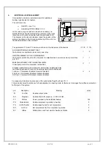
WINTER : the cooling cycle makes it possible to absorb energy (heat at low
temperature) from the external environment and to transfer it to the area to be
heated.
1. The compressor compresses the refrigerant fluid, placing it at high pressure
and high temperature.
2. The 4-way valve reverses the flow with respect to respect to SUMMER
operation.
3. In the plate exchanger, the water that returns to the system absorbs heat
from the refrigerant.
4. As it cools, the refrigerant condenses and becomes liquid.
5. The expansion valve causes a sudden drop in the pressure of the refrigerant,
which becomes very cold as its volume increases.
6. In the external coil, the cold refrigerant evaporates and absorbs heat from the
external air. In this phase, as the coil cools, it may freeze. This is why the
cycle is automatically reversed periodically for a short time so as to defrost it
2
1
3
4
5
6
7
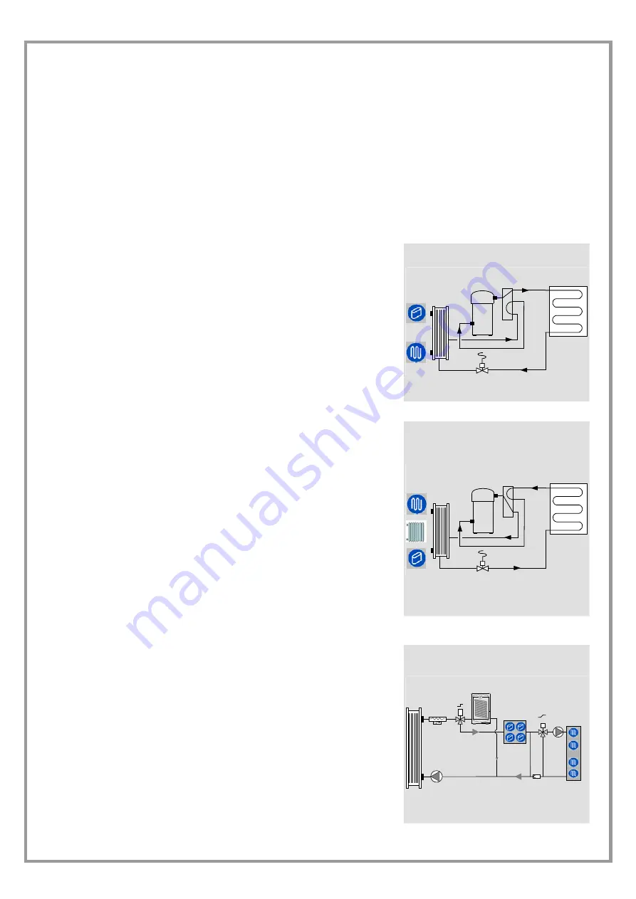
WATER CIRCUIT
The diagram on the side is indicative and includes optional components; check
with the installer about the system configuration used.
1. the electric heaters supplement the heating capacity supplied by the unit;
2. the 3-way valve diverts the water either towards the sanitary hot water
storage or towards the heating equipment;
3. sanitary hot water storage;
4. fan coil heating;
5. if the room needs to be heated, the 3-way valve diverts the water towards the
underfloor piping (all or in part); if instead the underfloor piping is satisfied, it
returns the water directly to the unit;
6. the pump keeps the water in circulation in the underfloor piping
7. underfloor
heating
8. the pump returns the water to the unit
1
2
3
4
5
6
7
8
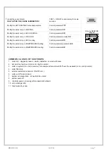
Summary of Contents for WSAN-XPR 21
Page 2: ......
Page 25: ...M0G940E8 00 04 07 08 pag 25...
Page 48: ...M0G940E8 00 04 07 08 pag 48...
Page 49: ...M0G940E8 00 04 07 08 pag 49 TECHNICAL DATA...
Page 59: ......


