background image

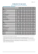
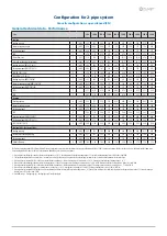
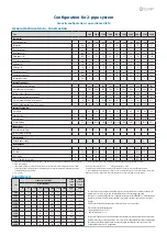
Configuration for 2-pipe system

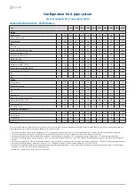
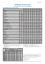
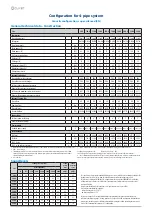
Acoustic configuration: super-silenced (EN)

General technical data - Construction

Size

90.4

100.4

110.4

120.4

140.4

160.4

180.4

200.4

220.4

240.4

Compressor

Type of compressors

-

Scroll

Scroll

Scroll

Scroll

Scroll

Scroll

Scroll

Scroll

Scroll

Scroll

Refrigerant

[kg]

47

47

47

57

64

65

79

79

81

95

No. of compressors

No

4

4

4

4

4

4

4

4

4

4

Rated power  (C1)

[HP]

45

50

55

60

70

80

90

100

100

120

Rated power  (C2)

[HP]

45

50

55

60

70

80

90

100

120

120

Std Capacity control steps

No

6

6

6

4

6

4

6

6

5

4

Oil charge (C1)

[l]

10

11

13

13

13

13

13

13

13

13

Oil charge (C2)

[l]

10

11

13

13

13

13

13

13

13

13

Refrigerant charge (C1)

1

[kg]

47

47

47

57

64

65

79

79

81

95

Refrigerant charge (C2)

1

[kg]

47

47

47

57

64

65

79

79

88

95

Refrigeration circuits

No

2

2

2

2

2

2

2

2

2

2

Internal exchanger

Type of cold user side exchanger

2

-

PHE

PHE

PHE

PHE

PHE

PHE

PHE

PHE

PHE

PHE

Type of hot user side exchanger

2

-

PHE

PHE

PHE

PHE

PHE

PHE

PHE

PHE

PHE

PHE

Cold user side exchanger water content

[l]

22

22

24

29

32

37

49

49

62

62

Hot user side exchanger water content

[l]

14,4

14,4

18,0

18,0

25,2

25,2

43,2

43,2

54,0

54,0

User side minimum system water content

3

[l]

1667

1719

2050

2383

2652

3018

3234

3234

4313

4517

Recovery side minimum system water content

3

[l]

1983

2130

2527

2887

3199

3596

3812

4097

5072

5320

External Section Fans

Type of fans

4

-

AX

AX

AX

AX

AX

AX

AX

AX

AX

AX

Number of fans

No

6

6

6

6

8

8

10

10

10

10

Type of motor

5

-

AC/P

AC/P

AC/P

AC/P

AC/P

AC/P

AC/P

AC/P

AC/P

AC/P

Standard airflow

[l/s]

30588

30588

29943

29570

40784

39924

50870

49776

49467

49159

Connections

User side water fittings

-

4”

4”

4”

4”

4”

5”

5”

5”

5”

5”

Recovery side water fittings

-

4”

4”

4”

4”

4”

5”

5”

5”

5”

5”

Power supply

Standard power supply

V

400/3~/50 400/3~/50 400/3~/50 400/3~/50 400/3~/50 400/3~/50 400/3~/50 400/3~/50 400/3~/50 400/3~/50

Electrical data

FLA - Total

A

205,2

216,5

233,3

262,1

299,3

328,3

387,9

416,9

457,1

497,3

FLI - Total

kW

117,7

128,6

138,2

155,8

180,7

201,9

231,2

252,4

275,8

299,2

M.I.C. - Value

6

A

455,6

466,9

483,7

512,5

619,2

648,2

657,6

686,6

726,8

767,0

M.I.C. - with soft start accessory

6

A

317,8

329,1

345,9

374,7

447,2

476,2

657,6

686,6

726,8

767,0

Sound levels

Size

Sound power level (dB)

Sound 
power 

level

Sound 

pressure 

level

Octave band (Hz)

63

125

250

500

1000

2000

4000

8000

dB(A)

dB(A)

90.4

87

84

84

82

82

79

65

56

86

66

100.4

87

84

84

82

82

79

65

56

86

66

110.4

87

84

84

82

82

79

65

56

86

66

120.4

88

85

85

83

83

80

66

57

86

66

140.4

88

85

85

83

83

80

66

57

86

66

160.4

89

86

86

84

84

81

67

58

87

67

180.4

96

92

91

88

84

79

73

67

90

69

200.4

96

92

91

88

84

79

73

67

90

69

220.4

97

93

92

89

85

80

74

68

90

69

240.4

97

93

92

89

85

80

74

68

90

70

The sound levels refer to standard unit with Axitop (no accessories) at full load, in test nominal conditions. The 
sound pressure level refers to 1 m. from the standard unit outer surface operating in open field.
Measures are according to UNI EN ISO 9614-2 regulations, with respect to the EUROVENT 8/1 certification, which 
provides for a tolerance of 3 dB(A) on the sound power level, which is the only acoustic data to be considered 
binding.
If unit is set without Axitop, the sound power level presents an increase up to 3 dB(A). 

Data referred to the following conditions.
- internal exchanger water = 12/7 °C 
- Ambient temperature = 35 °C

The indicated sound levels are only valid within the operating field of the standard unit at full load as indicated 
in the ‘Operating range - cooling ‘ graph in the  “Super-silenced EN” configuration. With outdoor air temperatures 
the unit operates at full load automatically increasing the airflow  and taking the same sound levels of the 
“Soundproofed Compressors SC” configuration.

1. Indicative values for standard units with po/-10% variation. The actual data are indicated on the label of the unit.
2. PHE = Plate exchanger
3. The minimum system water content calculated value does not consider the internal exchanger water content. With 

outdoor air low temperature applications or low medium requested loads, the minimum installation water volume is 
obtained doubling the indicated value

4. AX = axial fan

5. AC/P = asynchronous three-phase external rotor motor with phase cutting speed automatic control

Unbalance between phase max 2 %                    Voltage variation: max +/- 10%
Electrical data refer to standard units; according to the installed accessories, the data can suffer some variations.
6. M.I.C.=Maximum unit starting current. The M.I.C. value is obtained adding the max. compressor starting current of the 
highest size to the power input at max. admissible conditions (F.L.A.) of the remaining electric components.

Summary of Contents for WSAN-XSC3 MF 200.4

Page 1: ...M02M40N15 01 02 08 16 WSAN XSC3 MF 90 4 240 4 Installation and operating manual Multifunction heat pump with hot chilled simuoltaneous water production for outdoor installation ...

Page 2: ...the installation and maintenance cost for the life cycle of the system The purpose of this manual is to provide you with information that is useful from reception of the equipment through installation operational usage and finally disposal so that this advanced system offers the beat solution Yours faithfully CLIVET Spa The data contained in this manual is not binding and may be changed by the man...

Page 3: ... General description 4 2 Reception 6 3 Positioning 8 4 Water connections 10 5 Electrical connections 13 6 Start up 19 7 Control 29 8 Maintenance 41 9 Accessories 47 10 Decommissioning 51 11 Residual risks 52 12 Technical information 53 13 Dimensional drawings ...

Page 4: ...enced personnel they may cause damages to things and injuries people 1 4 Intended use Use the unit only for cooling heating water or a water and glycol mix keep to the limits foreseen in the technical schedule and in this manual The manufacturer accepts no responsibility if the equipment is used for any purpose other than the intended use 1 5 Installation Outdoor installation The positioning hydra...

Page 5: ...ns In case of breakdown or malfunction Immediately deactivate the unit Contact a service centre authorized by the manufacturer The installer must train the user particularly on Start up shutdown Set points change Standby mode Maintenance What to do what not to do in case of breakdown 1 12 Unit indentification The serial number label is positioned on the unit and allows to indentify all the unit fe...

Page 6: ...h advice of receipt to supplier and the carrier Any disputes must be made within 8 days from the date of the delivery Complaints after this period are invalid 2 1 Storage Observe external packaging instructions 2 2 Handling 1 Verify unit weight and handling equipment lifting capacity 2 Identify critical points during handling disconnected routes flights steps doors 3 Suitably protect the unit to p...

Page 7: ...t to damage the unit Keep packing material out of children s reach it may be dangerous Recycle and dispose of the packaging material in conformity with local regulations A B A Supports for handling remove after the handling B Remove the coil protective mesh before the start up ...

Page 8: ...nstall the unit raised from the ground verify unit weight and bearing point capacity verify that all bearing points are aligned and leveled condensate water draining consider the maximum possible snow level Avoid installations in places subject to flooding Protect the unit with suitable fence in order to avoid access to unauthorised personnel children vandals etc A correct circulation of the air i...

Page 9: ... mount support For details see 9 Accessories p 47 3 6 Condensate water When a heat pump is running it produces a considerable amount of water due to the defrosting cycles of the external coil The condensate must be disposed in order to avoid damages to people and things ...

Page 10: ...ion or empty the system in cases of long non use 4 3 Anti freeze solution The use of an anti freeze solution results in an increase in pressure drop Make sure that the glycol type utilized is inhibited not corrosive and compatible with the water circuit components Do not use different glicol mixture i e ethylene with propylene 4 4 Water flow rate The project water flow must be inside the exchanger...

Page 11: ...ection joint weld the union to the installation pipe perform the connection between the installation pipe and the evaporator using the joint Retirer le joint de connexion avant de souder le tuyau de l installation The rubber gasket might be irreparably damaged 4 8 Water filter Use filter with mesh pitch 1 6 mm It must be installed immediately in the water input of the unit in a position that is ea...

Page 12: ...clean water fill and drain the system several times 2 Apply additives to prevent corrosion fouling formation of mud and algae 3 Fill the plant 4 Execute leakage test 5 Isolate the pipes to avoid heat dispersions and formation of condensate 6 Leave various point of service free wells vent holes etc Neglecting the washing will lead to several filter cleaning interventions and at worst cases can caus...

Page 13: ... full load input full load power input at max admissible condition Electrical wiringdiagram Nr 5 2 Connections 1 Refer to the unit electrical diagram the number of the diagram is shown on the serial number label 2 Verify that the electrical supply has characteristics conforming to the data shown on the serial number label 3 Before starting work ensure the unit is isolated unable to be turned on an...

Page 14: ...0 x 5 Max bar Cu width mm 50 50 50 Tightening torque Nm 20 20 20 5 6 Connections performer by customer ALM cumulative fault signal QMP pump protection automatic device AP18 demand limit SA1 remote on off AP19 water reset SA1 1 second setpoint enabling switch APHI inverter pump recovery side SA6 sanitary hot water cycle switch APUI inverter user side SA7 summer winter switch APV 0 10V analogical ou...

Page 15: ...d sharing center 4 select Modify board setting 5 select Local area connection LAN 6 select Internet protocol version 4 TPC IPV4 and enter Property 7 set the IP address 192 168 1 100 8 set Subnet mask as 255 255 255 0 9 confirm OK 10 enter Start Windows button 11 write the command cmd and enter do it 12 write and run the command Ping 192 168 1 42 13 the message connection is OK will appear when suc...

Page 16: ... Distance up to 350 mt A User interface 2 Distance up to 700 mt B B1 KNX bus max 350 mt twisted pair with shield ø 0 8 mm EIB KNX cable marking recommende C PSX Mains power supply unit pwer supply unit N125 11 5WG1 125 1AB11 C1 AC 120 230V 50 60Hz D KNX bus max 350 mt ...

Page 17: ...BELDEN 3106A Every RS485 serial line must be set up using the In Out bus system Other types of networks are not allowed such as Star or Ring networks The difference in potential between the earth of the two RS485 devices that the cable shielding needs to be connected to must be lower than 7 V There must be suitable arresters to protect the serial lines from the effects of atmospheric discharges A ...

Page 18: ...1 down yellow startup red flashing software error red flashing communicating not possible fixed hardware error communication down 5 11 BACnet IP Option LED BSP communication with AP1 module LED BUS communication with BACnet green communication ok green ready for communication yellow software ok but communication with AP1 down yellow startup red flashing software error red BACnet server down fixed ...

Page 19: ...functional spaces 4 air flow correct return and supply no bypass no stratification 5 structure integrity 6 fans run freely 7 unit on vibration isolators 8 unit input water filter shut off valves for cleaning 9 vibration isolators on water connections 10 Minimum system water content 11 expansion tank indicative volume 5 system content 12 cleaned system 13 loaded system possible glycol solution corr...

Page 20: ...20 WSAN XSC3 MF 90 4 240 4 M02M40N15 01 6 4 Configuration for 2 pipe system ...

Page 21: ...dulation the standard unit can produce hot water even over the set point up to a settable limit temperature default 65 C Thanks to this setting the exchanger operation time hot user side is extended in desuperheater mode improving the unit efficiency of 5 compared to the desuperheater mode not active P0551 T InRecover P0550 Flow P0640 P0552 P0640 SetRecover P0640 P0553 P0552 DeltaTmpRec P0553 IstT...

Page 22: ...5 6 23 4 Safety temperature C 1 4 10 19 6 9 Electric Circuit Verify that the unit is connected to the ground plant Check the conductors are tightened as the vibrations caused by handling and transport might cause these to come loose Connect the unit by closing the sectioning device but leave it on OFF Check the voltage and line frequency values which must be within the limits 400 3 50 10 Check and...

Page 23: ...ssible to limit the absorbed electric power with an external signal 0 10 Vcc The higher the signal is the lower the number of compressors available to meet the thermal need If only P0002 EnDemandLimit 0 Path Main Menu Unit parameters Demand limit Step Display Action Menu Variable Keys Notes 1 Press 3 sec 2 Password Set Password 3 Press 4 Main menu Select Unit parameters 5 Unit parameters Select Se...

Page 24: ... Parameters Short description Description P0606 CSptLow setpoint temperature value when the air temperature value is AirAtSptLowC P0607 AirAtSetPointLowC external air temperature value where the calculated setpoint takes on the value given by CSptLow P0608 CSptHigh setpoint temperature value when the air temperature value is AirAtSptHigC P0609 AirAtSetPointHighC external air temperature value wher...

Page 25: ...t Water reset 6 Water reset Select Parameter 7 Set 8 Confirm 9 Press 3 sec 10 Select Local connections Path Main Menu Unit parameters Water reset Parameters Short description Description P0616 MaxCWRC Maximum correction to be applied to the setpoint Cooling P0617 SWRMaxC Value of the WR control signal corresponding to the correction of the set Cool equal to P0616 P0618 SWRMinC Value of the WR cont...

Page 26: ...cable Ø 0 8 mm use an EIB KNX cable Possible connections Tree star in out bus mixed It is not possible to use a ring connection No end of line resistor or terminator required There must be suitable arresters to protect the serial lines from the effects of atmospheric discharges The data line must be kept separate from the power conductors or powered at different voltage values and away from possib...

Page 27: ...2 setpoint3 plus optimal H2O temperature control MODE C The master manages the single cooling The master optimizes individual refrigerant circuits Active pumps only with active compressors P0658 2 P0657 0 C setpoint1 setpoint2 setpoint3 plus minimum pumps consumption need balanced system t1 t2 t3 Path Main Menu Unit parameters Master Slave Parameters Short description Description P0655 LNinstalled...

Page 28: ...constant and long operation with reduced load with frequent stop and start up of the compressor s can cause serious damages for the lack of oil return The above described operating conditions must be considered outside the operating limits In the event of compressor breakdown due to operating in the above mentioned conditions the guarantee will not be valid and Clivet spa declines any responsibili...

Page 29: ...tility side D T OutH2OUtilitySide Water outlet temperature utility side E ActualState On off eco pmp On F ActualMode Cooling Cooling PartRecover Cooling FullRecover Recover Heating Heating Recover 2 Installed compressors 1 0 Compressors ON example circuit 1 1 compr On circuit 2 0 compr On 50 Heating capacity 7 3 Keys Symbol Name Description Info Main menu Alarm Alarm display Cancel Exit Previous l...

Page 30: ...ullRecover Recover Heating Heating Recover 4 Confirm 5 Exit 7 6 Modify setpoint Step Display Action Menu Variable Keys Notes 1 Press 2 Main menu Select Unit parameters 3 Unit parameters Confirm Set Point 4 Select Set Point 5 Set Set Point 6 Confirm 7 Exit Parameters Short description Description P0583 SetPointCooling Setpoint Cool P0584 2SetPointCooling 2 Setpoint Cool Enable by remote switch P085...

Page 31: ... time 6 Confirm 7 Select Value 8 Set On Eco 9 Confirm 10 Exit Enable Scheduler Step Display Action Menu Variable Keys Notes 1 Press 3 sec 2 Password Set Password 3 Press 4 Main menu Select Unit Parameters 5 Select Option config 6 Set P0052 1 7 Press 3 sec Select Local connections Unit Parameters menu is displayed 7 8 Display the status Step Display Action Menu Variable Keys Notes 1 Press 2 Main me...

Page 32: ... STATA 8VHU VLGH 3XPS RPPDQG 8VHU VLGH 3XPS RPPDQG 8VHU VLGH 3XPS RPPDQG 8VHU VLGH QYHUWHU RPPDQG 8VHU VLGH QYHUWHU 6LJQDO 8VHU VLGH QYHUWHU 5HVHW 3XPS 2Q IRU QWL IUHH H QWL IUHH H HDWHUV 8VHU VLGH 8VHU VLGH ORZ 5HTXHVW LPLW ORZ HDWLQJ LPLW ORZ 5HFRYHU LPLW ORZ RROLQJ 8VHU VLGH 3XPS RXUV 8VHU VLGH 3XPS RXUV 8VHU VLGH 3XPS RXUV 1U CIRCUIT 1 STATA XUUHQW 6FKHPD 6XE RROLQJ XUUHQW FDSDFLW 3UHVVXUH UDW...

Page 33: ...SURWHFWLRQ 6RXUFH 6 VWHP RDG LJK 3UHVVXUH RPSUHVVRU 3URWHFWLRQ RPSUHVVRU 3URWHFWLRQ 6RXUFH DQ 3URWHFWLRQ LJK 3UHVVXUH RPSUHVVRU 3URWHFWLRQ RPSUHVVRU 3URWHFWLRQ 6RXUFH DQ 3URWHFWLRQ 1U ANALOGIC INPUT HPDQG LPLW 8VHU VLGH LIIHUHQWLDO 3UHVVXUH VZLWFK UHH FRROLQJ DWHU 7HPSHUDWXUH WHUQDO LU 7HPSHUDWXUH 5HFRYHU Q 7HPSHUDWXUH 5HFRYHU 2XW 7HPSHUDWXUH DELQHW 7HPSHUDWXUH DWHU 5HVHW 8VHU VLGH Q 7HPSHUDWXUH 8...

Page 34: ...SHQ UHH FRROLQJ 9DOYH ORVH 9 RROLQJ 9 HDWLQJ 9 RROLQJ 9 HDWLQJ ULHV HIURVW QMHFWLRQ 6RXUFH 3XPS RPPDQG RPSUHVVRU RPPDQG RPSUHVVRU RPPDQG LTXLG QMHFWLRQ LTXLG QMHFWLRQ 5HF9DOYH DWWHU 5HF9DOYH KLOOHU 5HF9DOYH 5HFRYHU 5HYHUVLQJ FOH 9DOYH ULHV HIURVW QMHFWLRQ 6RXUFH 3XPS RPPDQG RPSUHVVRU RPPDQG RPSUHVVRU RPPDQG LTXLG QMHFWLRQ LTXLG QMHFWLRQ 5HF9DOYH DWWHU 5HF9DOYH KLOOHU 5HF9DOYH 5HFRYHU 5HYHUVLQJ FOH...

Page 35: ... irreversible damage Example eE0001 Phase monitor Fault active alarm EE0003 Pum 1 faulty Ok resetted alarm Display of alarm step 1 3 Reset allarm step 4 10 Step Display Action Menu Variable Keys Notes 1 Press 2 Alarm list detail Press 3 Alarm list Select Alarm 4 Alarm list detail Press 3 sec 5 Password Set Enter password 6 Alarm list detail Press 7 Alarm list Select Alarm 8 Select Reset Executed 9...

Page 36: ...air temperature probe fault HW ee0030 DemandLimit Demand limit fault HW ee0031 WaterReset Water reset fault HW ee0032 External Humidity probe Error Relative humidity probe fault HW ee0033 T Quadro Ele Electrical panel temperature probe fault HW ee0035 YV Cool Open YV Cool opening fault 4P ee0036 YV Heat Open YV Heat opening fault 4P ee0037 YV Cool Close YV Cool closing fault 4P ee0038 YV Heat Clos...

Page 37: ... 3 discharge temperature probe fault HW Circuit 1 ee1025 T Source 1 Source 1 temperature probe fault HW Circuit 1 ee1026 T Source 2 Source 2 temperature probe fault HW Circuit 1 ee1027 T Suction Gas Suction temperature probe fault HW Circuit 1 ee1028 P Discharge High pressure probe fault HW Circuit 1 ee1029 P Suction Low pressure probe fault HW Circuit 1 ee1030 T GasRecovery Recovery exchanger gas...

Page 38: ...2013 Source Pump 1 protection Source side pump 1 overload protection Source 2 EE2014 Source Pump 2 protection Source side pump 2 overload protection Source 2 EE2015 Source Pump 3 protection Source side pump 3 overload protection Source 2 EE2018 Source side protection Source side ventilation overload protection Circuit 2 ee2022 T Discharge C1 1 Compressor 1 discharge temperature probe fault HW Circ...

Page 39: ... ECV 1 1 User side ECV connection problem HW Circuit 2 ee2071 Source ECV 1 1 Source side ECV 1 connection problem HW Circuit 2 ee2072 Source ECV 2 1 Source side ECV 2 connection problem HW Circuit 2 REFRIGERANT CIRCUIT ALARMS Num Name Description Category ff1005 Min overheating EEV1 Value of refrigerant superheat too low EEV1 user side Circuit 1 ff1006 Min overheating EEV2 Value of refrigerant sup...

Page 40: ...water temperature for defrost Circuit 2 ff2049 DFRTimeMax Defrost Time Circuit 2 HYDRAULIC CIRCUIT ALARMS Num Name Description Category iI0002 Water pressure User side low water pressure GP Ut iI0006 Flow switch utility side User side low flow rate GP Ut II0007 Freeze alarm User side Water Frost Protection Centrale ii0008 Pumps antifreeze alarm Pump activation Water Frost Protection Centrale II000...

Page 41: ...tical use service necessary intervention frequency months 1 6 12 1 presence corrosion X 2 panel fixing X 3 fan fixing X 4 coil cleaning X 5 water filter cleaning X 6 water quality ph weight of glycol X 7 check the exchanger efficiency X 8 circulating pumps X 9 check of the fixing and the insulation of the power lead X 10 check of the earthing cable X 11 electric panel cleaning X 12 capacity contac...

Page 42: ...ies from the surface Using an air pressure gun clean the aluminum surface of the battery be careful to direct the air in the opposite direction of the fan air movement Hold the gun parallel to the fins to avoid damages As an alternative vacumn cleaner can be used to suck impurities from the air input side Verify that the aluminum fins are not bent or damaged in the event of damages contact the aut...

Page 43: ...ondition of the insulations if necessary apply glue and and renew the seals 8 10 Water filter Check that no impurities prevent the correct passage of water 8 11 Flow Switch controls the operations remove incrustations from the palette 8 12 Compressor supply line shut off valve A A Supply line shut off valve Do not remove the seal Remove only if authorized by the manufacturer Please contact the mak...

Page 44: ...with glycoled solution 5 protect the exchanger from the air 6 remove the drain plugs to the pumps Any anti freeze liquid contained in the system should not be discharged freely as it is a pollutant It must be collected and reused Before starting a washing the plant Example emptying pump B It s recommended that the re start after the stopping period is performed by a qualified technician especially...

Page 45: ...M02M40N15 01 WSAN XSC3 MF 90 4 240 4 45 8 17 Compressor replacement ...

Page 46: ...46 WSAN XSC3 MF 90 4 240 4 M02M40N15 01 8 18 Exchanger replacement ...

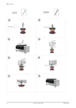
Page 47: ...M02M40N15 01 WSAN XSC3 MF 90 4 240 4 47 9 Accessories 9 1 Anti vibration mount support ...

Page 48: ...48 WSAN XSC3 MF 90 4 240 4 M02M40N15 01 ...

Page 49: ...on return valve 2 Cutoff valve 12 pressure switch of the charged system 3 Purge valve 13 Anti ice electric heater 4 Storage tank CSVX Couple of manually operated shut off valves 5 drain valve IFWX Steel mesh strainer on the water side 6 Cutoff valve PD Differential pressure switch 7 Steel mesh strainer T Temperature probe 8 Pressure gauge TWin Water inlet 9 Safety valve 6 Bar TW out Water outlet 1...

Page 50: ...off valve 12 pressure switch of the charged system 3 Purge valve 13 Anti ice electric heater 4 Storage tank CSVX Couple of manually operated shut off valves 5 drain valve IFWX Steel mesh strainer on the water side 6 Cutoff valve PD Differential pressure switch 7 Steel mesh strainer T Temperature probe 8 Pressure gauge TWin Water inlet 9 Safety valve 6 Bar TW out Water outlet 10 Electric pump ...

Page 51: ...its covered by the legislation in question are marked with the symbol on the side With the aim of protecting the environment all of our units are produced in compliance with Directive EC on waste electrical and electronic equipment RAEE The potential effects on the environment and on human health due to the presence of hazardous substances are shown in the use and maintenance manual in the section...

Page 52: ...self Periodically check that all of the panels are correctly closed and fixed If there is a fire the temperature of the refrigerant could reach values that in crease the pressure to beyond the safety valve with the consequent possible projection of the refrigerant itself or explosion of the circuit parts that remain isolated by the closure of the tap Do not remain in the vicinity of the safety val...

Page 53: ...capacity 6 kW 255 275 305 344 397 442 509 556 612 670 Heating capacity 6 kW 331 357 396 447 513 573 658 720 794 866 Total power input 6 kW 76 6 82 6 91 2 103 117 132 150 164 183 197 Global efficiency 8 kW 7 65 7 64 7 69 7 66 7 76 7 68 7 80 7 76 7 70 7 79 The Product is compliant with the ErP Energy Related Products European Directive It includes the Commission delegated Regulation EU No 811 2013 r...

Page 54: ...ity 6 kW 255 275 305 344 397 442 509 556 612 670 Heating capacity 6 kW 331 357 396 447 513 573 658 720 794 866 Total power input 6 kW 76 6 82 6 91 2 103 117 132 150 164 183 197 Global efficiency 8 kW 7 65 7 64 7 69 7 66 7 76 7 68 7 80 7 76 7 70 7 79 The Product is compliant with the ErP Energy Related Products European Directive It includes the Commission delegated Regulation EU No 811 2013 rated ...

Page 55: ... C Value 6 A 455 6 466 9 483 7 512 5 619 2 648 2 657 6 686 6 726 8 767 0 M I C with soft start accessory 6 A 317 8 329 1 345 9 374 7 447 2 476 2 657 6 686 6 726 8 767 0 Sound levels Size Sound power level dB Sound power level Sound pressure level Octave band Hz 63 125 250 500 1000 2000 4000 8000 dB A dB A 90 4 93 90 90 88 88 85 71 62 92 72 100 4 93 90 90 88 88 85 71 62 92 72 110 4 93 90 90 88 88 8...

Page 56: ...und power level dB Sound power level Sound pressure level Octave band Hz 63 125 250 500 1000 2000 4000 8000 dB A dB A 90 4 87 84 84 82 82 79 65 56 86 66 100 4 87 84 84 82 82 79 65 56 86 66 110 4 87 84 84 82 82 79 65 56 86 66 120 4 88 85 85 83 83 80 66 57 86 66 140 4 88 85 85 83 83 80 66 57 86 66 160 4 89 86 86 84 84 81 67 58 87 67 180 4 96 92 91 88 84 79 73 67 90 69 200 4 96 92 91 88 84 79 73 67 9...

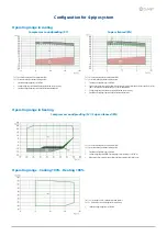
Page 57: ...is field the sound levels are the same of the compressor soundproofing SC acoustic configuration 3 Unit operating range with automatic staging of the compressor capacity 4 Standard unit operating range with air flow automatic modulation Operating range in heating Compressor soundproofing SC Super silenced EN Ta C external exchanger inlet air temperature D B To C internal exchanger outlet water tem...

Page 58: ...0 4 160 4 180 4 200 4 220 4 240 4 Qmin l s 8 5 8 5 10 4 10 4 13 6 13 6 18 6 18 6 19 2 19 8 Qmax l s 22 7 22 7 22 7 22 7 36 3 36 3 48 3 48 3 49 8 51 4 Overload and control device calibrations open closed value High pressure safety pressure switch kPa 4050 3300 Antifreeze protection C 3 5 5 High pressure safety valve kPa 4500 Low pressure safety valve kPa 2950 Max no of compressor starts per hour n ...

Page 59: ...city 6 kW 255 275 305 344 397 442 509 556 612 670 Total recovery heating capacity 6 kW 331 357 396 447 513 573 658 720 794 866 Total power input 6 kW 76 6 82 6 91 2 103 117 132 150 164 183 197 Global efficiency 8 kW 7 65 7 64 7 69 7 66 7 76 7 68 7 80 7 76 7 70 7 79 The Product is compliant with the ErP Energy Related Products European Directive It includes the Commission delegated Regulation EU No...

Page 60: ...6 kW 255 275 305 344 397 442 509 556 612 670 Total recovery heating capacity 6 kW 331 357 396 447 513 573 658 720 794 866 Total power input 6 kW 76 6 82 6 91 2 103 117 132 150 164 183 197 Global efficiency 8 kW 7 65 7 64 7 69 7 66 7 76 7 68 7 80 7 76 7 70 7 79 The Product is compliant with the ErP Energy Related Products European Directive It includes the Commission delegated Regulation EU No 811 ...

Page 61: ...9 483 7 512 5 619 2 648 2 657 6 686 6 726 8 767 0 M I C with soft start accessory 6 A 317 8 329 1 345 9 374 7 447 2 476 2 657 6 686 6 726 8 767 0 Sound levels Size Sound power level dB Sound power level Sound pressure level Octave band Hz 63 125 250 500 1000 2000 4000 8000 dB A dB A 90 4 93 90 90 88 88 85 71 62 92 72 100 4 93 90 90 88 88 85 71 62 92 72 110 4 93 90 90 88 88 85 71 62 92 72 120 4 93 ...

Page 62: ...d power level Sound pressure level Octave band Hz 63 125 250 500 1000 2000 4000 8000 dB A dB A 90 4 87 84 84 82 82 79 65 56 86 66 100 4 87 84 84 82 82 79 65 56 86 66 110 4 87 84 84 82 82 79 65 56 86 66 120 4 88 85 85 83 83 80 66 57 86 66 140 4 88 85 85 83 83 80 66 57 86 66 160 4 89 86 86 84 84 81 67 58 87 67 180 4 96 92 91 88 84 79 73 67 90 69 200 4 96 92 91 88 84 79 73 67 90 69 220 4 97 93 92 89 ...

Page 63: ...this field the sound levels are the same of the compressor soundproofing SC acoustic configuration 3 Unit operating range with automatic staging of the compressor capacity 4 Standard unit operating range with air flow automatic modulation Operating range in heating Compressor soundproofing SC Super silenced EN Ta C external exchanger inlet air temperature D B To C internal exchanger outlet water t...

Page 64: ... 200 4 220 4 240 4 Qmin l s 8 5 8 5 10 4 10 4 13 6 13 6 18 6 18 6 19 2 19 8 Qmax l s 22 7 22 7 22 7 22 7 36 3 36 3 48 3 48 3 49 8 51 4 Overload and control device calibrations open closed value High pressure safety pressure switch kPa 4050 3300 Antifreeze protection C 3 5 5 High pressure safety valve kPa 4500 Low pressure safety valve kPa 2950 Max no of compressor starts per hour n 10 High compres...

Page 65: ...g 590 601 615 633 590 601 615 633 Shipping weight kg 2971 3037 3109 3207 2971 3037 3109 3207 Operating weight kg 3119 3185 3259 3362 3119 3185 3259 3362 Size SC EXC EN EXC 90 4 100 4 110 4 120 4 90 4 100 4 110 4 120 4 Container shipping length mm 4209 4209 4209 4209 4209 4209 4209 4209 Container shipping depth mm 2343 2343 2343 2343 2343 2343 2343 2343 Container shipping height mm 2484 2484 2484 2...

Page 66: ...hipping weight kg 3707 3777 3707 3777 Operating weight kg 3932 4006 3932 4006 Size SC EXC EN EXC 140 4 160 4 140 4 160 4 Container shipping length mm 5578 5578 5578 5578 Container shipping depth mm 2343 2343 2343 2343 Container shipping height mm 2484 2484 2484 2484 The presence of optional accessories may result in a substantial variation of the weights shown in the table Fan diffusers are separa...

Page 67: ...491 513 527 485 491 513 527 W6 Supporting point kg 487 494 507 524 487 494 507 524 Shipping weight kg 4479 4539 4764 4925 4479 4539 4764 4925 Operating weight kg 4769 4830 5068 5234 4769 4830 5068 5234 Size SC EXC EN EXC 180 4 200 4 220 4 240 4 180 4 200 4 220 4 240 4 Container shipping length mm 6460 6460 6460 6460 6460 6460 6460 6460 Container shipping depth mm 2343 2343 2343 2343 2343 2343 2343...

Page 68: ... info clivetcomercial es CLIVET ESPAÑA S A U Service and Maintenance Division Calle Real de Burgos n 12 28860 Paracuellos del Jarama Madrid España Tel 34 91 6658280 Fax 34 91 6657806 info clivet es CLIVET GmbH Hummelsbütteler Steindamm 84 22851 Norderstedt Germany Tel 49 0 40 32 59 57 0 Fax 49 0 40 32 59 57 194 info de clivet com CLIVET RUSSIA Elektrozavodskaya st 24 office 509 107023 Moscow Russi...

Reviews: