background image

44 WSAT-XEM 

50.4-120.4 

M0L240E16-01

9.4  Anti-vibration mount support

Summary of Contents for WSAT-XEM 50.4

Page 1: ...M0L240E16 01 06 06 16 WSAT XEM 50 4 120 4 Installation and operating manual Air cooled water chiller for outdoor installation ...

Page 2: ...the installation and maintenance cost for the life cycle of the system The purpose of this manual is to provide you with information that is useful from reception of the equipment through installation operational usage and finally disposal so that this advanced system offers the beat solution Yours faithfully CLIVET Spa The data contained in this manual is not binding and may be changed by the man...

Page 3: ...eneral description 4 2 Reception 6 3 Positioning 8 4 Water connections 9 5 Electrical connections 12 6 Start up 19 7 Control 27 8 Maintenance 39 9 Accessories 43 10 Decommissioning 48 11 Residual risks 49 12 Technical information 50 13 Dimensional drawings 5 ...

Page 4: ...d personnel they may cause damages to things and injuries people 1 4 Intended use Use the unit only for cooling heating water or a water and glycol mix for air conditioning only keep to the limits foreseen in the technical schedule and in this manual The manufacturer accepts no responsibility if the equipment is used for any purpose other than the intended use 1 5 Installation The positioning hydr...

Page 5: ... In case of breakdown or malfunction Immediately deactivate the unit Contact a service centre authorized by the manufacturer The installer must train the user particularly on Start up shutdown Set points change Standby mode Maintenance What to do what not to do in case of breakdown 1 12 Unit indentification The serial number label is positioned on the unit and allows to indentify all the unit feat...

Page 6: ...advice of receipt to supplier and the carrier Any disputes must be made within 8 days from the date of the delivery Complaints after this period are invalid 2 1 Storage Observe external packaging instructions 2 2 Handling 1 Verify unit weight and handling equipment lifting capacity 2 Identify critical points during handling disconnected routes flights steps doors 3 Suitably protect the unit to pre...

Page 7: ...rial out of children s reach it may be dangerous Recycle and dispose of the packaging material in conformity with local regulations A Supports for handling remove after the handling B Remove the coil protective mesh before the start up 2 4 Anti vibration mount support Option For details see 9 Accessories p 43 ...

Page 8: ...t and bearing point capacity verify that all bearing points are aligned and leveled install the unit raised from the ground consider the maximum possible snow level A correct circulation of the air is mandatory to guarantee the good unit operating Protect the unit with suitable fence in order to avoid access to unauthorised personnel children vandals etc Avoid therefore obstacles to the airflow di...

Page 9: ...earing to clean system 4 2 Risk of freezing If the unit or the relative water connections are subject to temperatures close to 0 C mix water with glycol or safeguard the pipes with heating cables placed under the insulation or empty the system in cases of long non use 4 3 Anti freeze solution The use of an anti freeze solution results in an increase in pressure drop Make sure that the glycol type ...

Page 10: ... system 2 7 9 13 3 1 14 UNIT 6 10 12 4 5 8 15 F 11 1 antivibration joints 9 safety valve 2 piping support 10 Flow Switch 3 exchanger chemical cleaning bypass 11 pressure gauge 4 drain valve 12 thermometer 5 vent 13 filter 6 shut off valve 14 Internal storage tank 7 Pump circulating pump 15 Cleaning system bypass 8 expansion vessel 4 8 Water filter Use filter with mesh pitch 1 6 mm It must be insta...

Page 11: ...tors storage tank free cooling coil 1 Carefully wash the system with clean water fill and drain the system several times 2 Apply additives to prevent corrosion fouling formation of mud and algae 3 Fill the plant 4 Vent the system 5 Execute leakage test 6 Isolate the pipes to avoid heat dispersions and formation of condensate 7 Leave various point of service free wells vent holes etc Neglecting the...

Page 12: ...lar Voltage F L A full load ampere absorbed current at maximum admitted conditions F L I full load input full load power input at max admissible condition Electrical wiringdiagram Nr 5 2 Connections 1 Refer to the unit electrical diagram the number of the diagram is shown on the serial number label 2 Verify that the electrical supply has characteristics conforming to the data shown on the serial n...

Page 13: ...ain switch connections Size 50 4 55 4 60 4 65 4 70 4 Min cable section Cu mm 1x50 1x50 1x50 1x95 1x95 Max cable section Cu mm 1x95 1x95 1x95 1x150 1x150 Min bar Cu section mm Max bar Cu width mm 25 25 25 32 32 Tightening torque Nm 9 9 9 20 20 Size 80 4 90 4 100 4 110 4 120 4 Min cable section Cu mm 1x95 1x95 1x95 1x95 1x95 Max cable section Cu mm 1x150 1x185 1x185 1x185 1x185 Min bar Cu section mm...

Page 14: ...witch APV 0 10V analogical output for free cooling management SA7 summer winter switch HLC1 4 compressor status signal lamp SA9 cooling thermostat HLR alarm signal lamp electrical heater electrical panel selector SQ1 Flow Switch KMP evaporator pump contactor YVHS1 sanitary hot water valve 5 6 Remote ON OFF Do not perform short On Off cycles Do not use the remote On Off with thermoregulation functi...

Page 15: ...sharing center 4 select Modify board setting 5 select Local area connection LAN 6 select Internet protocol version 4 TPC IPV4 and enter Property 7 set the IP address 192 168 1 100 8 set Subnet mask as 255 255 255 0 9 confirm OK 10 enter Start Windows button 11 write the command cmd and enter do it 12 write and run the command Ping 192 168 1 42 13 the message connection is OK will appear when succe...

Page 16: ...N 3106A Every RS485 serial line must be set up using the In Out bus system Other types of networks are not allowed such as Star or Ring networks The difference in potential between the earth of the two RS485 devices that the cable shielding needs to be connected to must be lower than 7 V There must be suitable arresters to protect the serial lines from the effects of atmospheric discharges A 120 o...

Page 17: ...own yellow startup red flashing software error red flashing communicating not possible fixed hardware error communication down 5 10 BACnet IP Option LED BSP communication with AP1 module LED BUS communication with BACnet green communication ok green ready for communication yellow software ok but communication with AP1 down yellow startup red flashing software error red BACnet server down fixed har...

Page 18: ...Distance up to 350 mt C PSX Mains power supply unit pwer supply unit N125 11 5WG1 125 1AB11 2 Distance up to 700 mt C1 AC 120 230V 50 60Hz A User interface D KNX bus max 350 mt B B1 KNX bus max 350 mt twisted pair with shield ø 0 8 mm EIB KNX cable marking recommende ...

Page 19: ...rity 5 fans run freely 6 unit on vibration isolators 7 unit input water filter shut off valves for cleaning 8 vibration isolators on water connections 9 expansion tank indicative volume 5 system content 10 Close all drain valves in the low points of the unit hydraulic circuit 11 Close all vent valves in the high points of the unit hydraulic circuit 12 cleaned system 13 loaded system possible glyco...

Page 20: ...re C 1 4 10 19 6 6 Electric Circuit Verify that the unit is connected to the ground plant Check the conductors are tightened as the vibrations caused by handling and transport might cause these to come loose Connect the unit by closing the sectioning device but leave it on OFF Check the voltage and line frequency values which must be within the limits 400 3 50 10 Check and adjust the phase balance...

Page 21: ...fication can cause irreversible damages It is possible to limit the absorbed electric power with an external signal 0 10 Vcc The higher the signal is the lower the number of compressors available to meet the thermal need If only P0002 EnDemandLimit 0 Path Main Menu Unit parameters Demand limit Step Display Action Menu Variable Keys Notes 1 Press 3 sec 2 Password Set Password 3 Press 4 Main menu Se...

Page 22: ...arameters Short description Description P0606 CSptLow setpoint temperature value when the air temperature value is AirAtSptLowC P0607 AirAtSetPointLowC external air temperature value where the calculated setpoint takes on the value given by CSptLow P0608 CSptHigh setpoint temperature value when the air temperature value is AirAtSptHigC P0609 AirAtSetPointHighC external air temperature value where ...

Page 23: ...Water reset 6 Water reset Select Parameter 7 Set 8 Confirm 9 Press 3 sec 10 Select Local connections Path Main Menu Unit parameters Water reset Parameters Short description Description P0616 MaxCWRC Maximum correction to be applied to the setpoint Cooling P0617 SWRMaxC Value of the WR control signal corresponding to the correction of the set Cool equal to P0616 P0618 SWRMinC Value of the WR contro...

Page 24: ...ble Ø 0 8 mm use an EIB KNX cable Possible connections Tree star in out bus mixed It is not possible to use a ring connection No end of line resistor or terminator required There must be suitable arresters to protect the serial lines from the effects of atmospheric discharges The data line must be kept separate from the power conductors or powered at different voltage values and away from possible...

Page 25: ...setpoint3 plus optimal H2O temperature control MODE C The master manages the single cooling The master optimizes individual refrigerant circuits Active pumps only with active compressors P0658 2 P0657 0 C setpoint1 setpoint2 setpoint3 plus minimum pumps consumption need balanced system t1 t2 t3 Path Main Menu Unit parameters Master Slave Parameters Short description Description P0655 LNinstalledUn...

Page 26: ...erating circuit compressor discharge liquid intake The measurements must be kept and made available during maintenance interventions 6 16 Operating at reduced load The units are equipped with partialization steps and they can therefore operate with reduced loads However a constant and long operation with reduced load with frequent stop and start up of the compressor s can cause serious damages for...

Page 27: ...ature utility side D T OutH2OUtilitySide Water outlet temperature utility side E ActualState On off eco pmp On F ActualMode Cool water cooling Heat Heating not used 2 Installed compressors 1 0 Compressors ON example circuit 1 1 compr On circuit 2 0 compr On 50 Heating capacity 7 3 Keys Symbol Name Description Info Main menu Alarm Alarm display Cancel Exit Previous level Keyboard settings Up Increa...

Page 28: ...ing Heat HEATING 4 Confirm 5 Exit 7 6 Modify setpoint Step Display Action Menu Variable Keys Notes 1 Press 2 Main menu Select Unit parameters 3 Unit parameters Confirm Set Point 4 Select Set Point 5 Set Set Point 6 Confirm 7 Exit Parameters Short description Description P0583 SetPointCooling Setpoint Cool P0584 2SetPointCooling 2 Setpoint Cool Enable by remote switch P0855 SetPointECOCooling Econo...

Page 29: ...ime 6 Confirm 7 Select Value 8 Set On Eco 9 Confirm 10 Exit Enable Scheduler Step Display Action Menu Variable Keys Notes 1 Press 3 sec 2 Password Set Password 3 Press 4 Main menu Select Unit Parameters 5 Select Option config 6 Set P0052 1 7 Press 3 sec Select Local connections Unit Parameters menu is displayed 7 8 Display the status Step Display Action Menu Variable Keys Notes 1 Press 2 Main menu...

Page 30: ...S RPPDQG 8VHU VLGH 3XPS RPPDQG 8VHU VLGH 3XPS RPPDQG 8VHU VLGH QYHUWHU RPPDQG 8VHU VLGH QYHUWHU 6LJQDO 8VHU VLGH QYHUWHU 5HVHW 3XPS 2Q IRU QWL IUHH H QWL IUHH H HDWHUV 8VHU VLGH 8VHU VLGH ORZ 5HTXHVW LPLW ORZ HDWLQJ LPLW ORZ 5HFRYHU LPLW ORZ RROLQJ 8VHU VLGH 3XPS RXUV 8VHU VLGH 3XPS RXUV 8VHU VLGH 3XPS RXUV 1U CIRCUIT 1 STATA XUUHQW 6FKHPD 6XE RROLQJ XUUHQW FDSDFLW 3UHVVXUH UDWLR QYHORSH RQH QYHOR...

Page 31: ...VWHP RDG LJK 3UHVVXUH RPSUHVVRU 3URWHFWLRQ RPSUHVVRU 3URWHFWLRQ 6RXUFH DQ 3URWHFWLRQ LJK 3UHVVXUH RPSUHVVRU 3URWHFWLRQ RPSUHVVRU 3URWHFWLRQ 6RXUFH DQ 3URWHFWLRQ 1U ANALOGIC INPUT HPDQG LPLW 8VHU VLGH LIIHUHQWLDO 3UHVVXUH VZLWFK UHH FRROLQJ DWHU 7HPSHUDWXUH WHUQDO LU 7HPSHUDWXUH 5HFRYHU Q 7HPSHUDWXUH 5HFRYHU 2XW 7HPSHUDWXUH DELQHW 7HPSHUDWXUH DWHU 5HVHW 8VHU VLGH Q 7HPSHUDWXUH 8VHU VLGH 2XW 7HPSHUD...

Page 32: ...H ORVH 9 RROLQJ 9 HDWLQJ 9 RROLQJ 9 HDWLQJ ULHV HIURVW QMHFWLRQ 6RXUFH 3XPS RPPDQG RPSUHVVRU RPPDQG RPSUHVVRU RPPDQG LTXLG QMHFWLRQ LTXLG QMHFWLRQ 5HF9DOYH DWWHU 5HF9DOYH KLOOHU 5HF9DOYH 5HFRYHU 5HYHUVLQJ FOH 9DOYH ULHV HIURVW QMHFWLRQ 6RXUFH 3XPS RPPDQG RPSUHVVRU RPPDQG RPSUHVVRU RPPDQG LTXLG QMHFWLRQ LTXLG QMHFWLRQ 5HF9DOYH DWWHU 5HF9DOYH KLOOHU 5HF9DOYH 5HFRYHU 5HYHUVLQJ FOH 9DOYH 1U ANALOGIC O...

Page 33: ... resets can cause irreversible damage Example eE0001 Phase monitor Fault active alarm EE0003 Pum 1 faulty Ok resetted alarm Display of alarm step 1 3 Reset allarm step 4 10 Step Display Action Menu Variable Keys Notes 1 Press 2 Alarm list detail Press 3 Alarm list Select Alarm 4 Alarm list detail Press 3 sec 5 Password Set Enter password 6 Alarm list detail Press 7 Alarm list Select Alarm 8 Select...

Page 34: ...r temperature probe fault HW ee0030 DemandLimit Demand limit fault HW ee0031 WaterReset Water reset fault HW ee0032 External Humidity probe Error Relative humidity probe fault HW ee0033 T Quadro Ele Electrical panel temperature probe fault HW ee0035 YV Cool Open YV Cool opening fault 4P ee0036 YV Heat Open YV Heat opening fault 4P ee0037 YV Cool Close YV Cool closing fault 4P ee0038 YV Heat Close ...

Page 35: ... discharge temperature probe fault HW Circuit 1 ee1025 T Source 1 Source 1 temperature probe fault HW Circuit 1 ee1026 T Source 2 Source 2 temperature probe fault HW Circuit 1 ee1027 T Suction Gas Suction temperature probe fault HW Circuit 1 ee1028 P Discharge High pressure probe fault HW Circuit 1 ee1029 P Suction Low pressure probe fault HW Circuit 1 ee1030 T GasRecovery Recovery exchanger gas t...

Page 36: ...13 Source Pump 1 protection Source side pump 1 overload protection Source 2 EE2014 Source Pump 2 protection Source side pump 2 overload protection Source 2 EE2015 Source Pump 3 protection Source side pump 3 overload protection Source 2 EE2018 Source side protection Source side ventilation overload protection Circuit 2 ee2022 T Discharge C1 1 Compressor 1 discharge temperature probe fault HW Circui...

Page 37: ...CV 1 1 User side ECV connection problem HW Circuit 2 ee2071 Source ECV 1 1 Source side ECV 1 connection problem HW Circuit 2 ee2072 Source ECV 2 1 Source side ECV 2 connection problem HW Circuit 2 REFRIGERANT CIRCUIT ALARMS Num Name Description Category ff1005 Min overheating EEV1 Value of refrigerant superheat too low EEV1 user side Circuit 1 ff1006 Min overheating EEV2 Value of refrigerant super...

Page 38: ...ter temperature for defrost Circuit 2 ff2049 DFRTimeMax Defrost Time Circuit 2 HYDRAULIC CIRCUIT ALARMS Num Name Description Category iI0002 Water pressure User side low water pressure GP Ut iI0006 Flow switch utility side User side low flow rate GP Ut II0007 Freeze alarm User side Water Frost Protection Centrale ii0008 Pumps antifreeze alarm Pump activation Water Frost Protection Centrale II0009 ...

Page 39: ...ating limits etc critical use service necessary intervention frequency months 1 6 12 1 presence corrosion X 2 panel fixing X 3 fan fixing X 4 coil cleaning X 5 water filter cleaning X 6 check the exchanger efficiency X 7 circulating pumps X 8 check of the fixing and the insulation of the power lead X 9 check of the earthing cable X 10 electric panel cleaning X 11 capacity contactor status X 12 ter...

Page 40: ...g When restarting refer to what is indicated in the start up section Schedule technical assistance in advance to avoid hitches and to guarantee that the system can be used when required 8 5 Air coil Contact with the exchanger fins can cause cuts wear protective gloves to perform the above described operations It is extremely important that the battery gives the maximum thermal exchange therefore i...

Page 41: ...exchanger The clearing must be effected with circulation opposite to the usual one with a speed at least 1 5 times higher than the nominal one with an appropriate product moderately acid 95 water 5 phosphoric acid after the cleaning rinse with water to inhibit the action of any residual product 8 8 Circulating pumps Check no leaks bearing status anomalies are highlighted by abnormal noise and vibr...

Page 42: ...ety fill the exchanger with glycoled solution 6 protect the exchanger from the air 7 remove the drain plugs to the pumps Any anti freeze liquid contained in the system should not be discharged freely as it is a pollutant It must be collected and reused Before starting a washing the plant Example emptying pump It s recommended that the re start after the stopping period is performed by a qualified ...

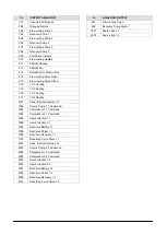
Page 43: ...sure switch user side EVPT2 Plate evaporator 2 circuits R13 Evaporator gropu heater user side BT1 Probes of air return entering water temperature BT2 Probes of air supply leaving water temperature SPA1 Differential pressure switch user water side PU Pump user side ON OFF pump VSU Water safety valve R19 Hydronic assembly heaters SPA2 System water pressure switch user side EVPT2 Plate evaporator 2 c...

Page 44: ...44 WSAT XEM 50 4 120 4 M0L240E16 01 9 4 Anti vibration mount support ...

Page 45: ...M0L240E16 01 WSAT XEM 50 4 120 4 45 ...

Page 46: ...ity and Production of heat capacity using recovery equals 50 of the heat capacity request To prevent constant switching in the unit s refrigeration circuit it is necessary to install a storage tank with an adequate capacity in the system s hot water circuit In the absence of hot water circulating in the recovery exchanger the maximum entering air temperature is reduced by approximately 2 C compare...

Page 47: ...sidered in operation when it is fed with the flow of water to be heated When the temperature of the water to be heated is particularly low it is wise to insert a flow control valve into the system water circuit in order to maintain the temperature at the recovery output at above 35 C and thus avoid the condensation of the refrigerant into the partial energy recovery device The recovery exchanger m...

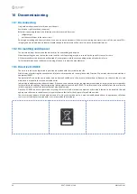
Page 48: ...s covered by the legislation in question are marked with the symbol on the side With the aim of protecting the environment all of our units are produced in compliance with Directive EC on waste electrical and electronic equipment RAEE The potential effects on the environment and on human health due to the presence of hazardous substances are shown in the use and maintenance manual in the section o...

Page 49: ...lf Periodically check that all of the panels are correctly closed and fixed If there is a fire the temperature of the refrigerant could reach values that in crease the pressure to beyond the safety valve with the consequent possible projection of the refrigerant itself or explosion of the circuit parts that remain isolated by the closure of the tap Do not remain in the vicinity of the safety valve...

Page 50: ...C Entering external exchanger air temperature 35 C 5 Data compliant to Standard AHRI 550 590 referred to the following conditions internal exchanger water temperature 6 7 C Water flow rate 0 043 l s per kW Entering external exchanger air temperature 35 C Evaporator fouling factor 0 18 x 10 4 m2 K 13 6 Version General technical data Performance Size 70 4 80 4 90 4 100 4 110 4 120 4 Cooling Cooling ...

Page 51: ... 100 4 93 90 90 88 88 85 71 62 92 72 110 4 93 90 90 88 88 85 71 62 92 72 120 4 93 90 90 88 88 85 71 62 92 72 Unit with HEDIF Diffuser for high efficiency axial fan option Size Sound power level Sound pressure level 70 4 86 66 80 4 86 66 90 4 86 66 100 4 90 70 110 4 90 70 120 4 90 70 Sound levels refer to units with full load under nominal test conditions The sound pressure level refers to a distan...

Page 52: ...allo scambiatore esterno 35 C 4 PHE scambiatore a piastre 5 AX ventilatore assiale Sound level Standard unit Size Sound power level dB Sound power level Sound pressure level Octave band Hz 63 125 250 500 1000 2000 4000 8000 dB A dB A 70 4 108 102 80 80 70 63 53 52 88 68 80 4 108 102 80 80 72 65 55 53 88 68 90 4 108 102 80 81 73 64 55 53 88 68 100 4 112 106 84 85 76 68 58 56 92 72 110 4 112 106 84 ...

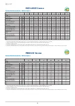
Page 53: ...ng EXCELLENCE Version PREMIUM Version Selecting the CREFO Device to reduce the consumption levels of on off fans on the external section option the unit operation is not possible with outdoor air temperature lower than 15 C Twu C Internal exchanger outlet water temperature Tae C External exchanger inlet air temperature 1 Standard unit operating range at full load 2 Standard unit operating range wi...

Page 54: ... switch kPa 4050 3300 Low pressure alarm gas side kPa 450 600 Antifreeze protection C 4 0 6 0 High pressure safety valve gas side kPa 4500 Low pressure safety valve gas side kPa 3000 Max no of compressor starts per hour gas side n 10 Differential pressure switch water side kPa 3 5 Max pressure without hydronic assembly water side kPa 1000 Max pressure with hydronic assembly water side kPa 600 Safe...

Page 55: ...de exchanger water outlet optional Size 50 4 55 4 60 4 65 4 OD internal exchanger mm 88 9 88 9 88 9 88 9 OD1 partial recovery mm 48 3 48 3 48 3 48 3 OD2 total recovery mm 88 9 88 9 88 9 88 9 Length mm 4400 4400 4400 4400 Height mm 1800 1800 1800 1800 Depth mm 1812 1812 1812 1812 W1 Supporting point kg 434 440 457 481 W2 Supporting point kg 294 300 313 315 W3 Supporting point kg 439 450 461 500 W4 ...

Page 56: ...y side exchanger water outlet optional Size 70 4 80 4 90 4 OD internal exchanger mm 88 9 88 9 88 9 OD1 partial recovery mm 48 3 48 3 48 3 OD2 total recovery mm 88 9 88 9 88 9 Length mm 4400 4400 4400 Height mm 2300 2300 2300 Height with AXITOP mm 2460 2460 2460 Depth mm 2250 2250 2250 W1 Supporting point kg 694 721 760 W2 Supporting point kg 441 454 471 W3 Supporting point kg 717 748 793 W4 Suppor...

Page 57: ...ery side exchanger water outlet optional Size 100 4 110 4 120 4 OD internal exchanger mm 114 3 114 3 114 3 OD1 partial recovery mm 60 3 60 3 60 3 OD2 total recovery mm 114 3 114 3 114 3 Length mm 5200 5200 5200 Height mm 2300 2300 2300 Height with AXITOP mm 2460 2460 2460 Depth mm 2250 2250 2250 W1 Supporting point kg 883 909 948 W2 Supporting point kg 557 564 593 W3 Supporting point kg 905 932 97...

Page 58: ...ery side exchanger water inlet optional 10 Recovery side exchanger water outlet optional Size 70 4 80 4 OD internal exchanger mm 88 9 88 9 OD1 partial recovery mm 48 3 48 3 Length mm 3800 3800 Height mm 2300 2300 Height with AXITOP mm 2460 2460 Depth mm 2250 2250 W1 Supporting point kg 650 681 W2 Supporting point kg 392 410 W3 Supporting point kg 675 712 W4 Supporting point kg 418 440 Shipping wei...

Page 59: ...ional 10 Recovery side exchanger water outlet optional Size 90 4 100 4 110 4 OD internal exchanger mm 88 9 114 3 114 3 OD1 partial recovery mm 48 3 60 3 60 3 Length mm 4400 4400 4400 Height mm 2300 2300 2300 Height with AXITOP mm 2460 2460 2460 Depth mm 2250 2250 2250 W1 Supporting point kg 744 820 866 W2 Supporting point kg 458 482 490 W3 Supporting point kg 774 842 889 W4 Supporting point kg 488...

Page 60: ... with pumps optional 9 Recovery side exchanger water inlet optional 10 Recovery side exchanger water outlet optional Size 120 4 OD internal exchanger mm 114 3 OD1 partial recovery mm 60 3 Length mm 5200 Height mm 2300 Height with AXITOP mm 2460 Depth mm 2250 W1 Supporting point kg 955 W2 Supporting point kg 566 W3 Supporting point kg 979 W4 Supporting point kg 590 Shipping weight kg 3020 Operating...

Page 61: ...Page intentionally blank ...

Page 62: ...el 34 93 8606248 Fax 34 93 8855392 info clivetcomercial com CLIVET ESPAÑA S A U Service and Maintenance Division Calle Real de Burgos Nº 12 28860 Paracuellos del Jarama Madrid España Tel 34 91 6658280 Fax 34 91 6657806 info clivet es CLIVET GmbH Hummelsbütteler Steindamm 84 22851 Norderstedt Germany Tel 49 0 40 32 59 57 0 Fax 49 0 40 32 59 57 194 info de clivet com CLIVET RUSSIA Elektrozavodskaya ...

Reviews: