25
STEP 16 – Solid Steel Shaft Torsion Spring
Installation
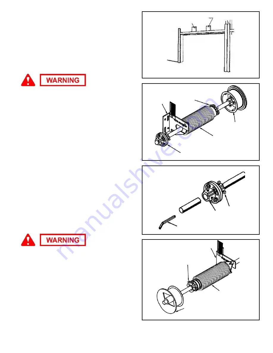
Step 16-1:
Measure from top of door to center of end bearing.
Use this measurement, draw a line at the same height for shaft
location and mount both 2"x 6" wood jambs. (FIG. 16-A)
Important:
The wood anchor pad must be made of a Grade 2 or
better southern yellow pine (also known as southern pine or
yellow pine). Other acceptable types of wood for this application
are beech, birch, hickory, and oak. The wood must be free of
splits and cracks.
Do not use wood labeled as spruce pine fir
(or SPF).
It is important that the torsion spring assembly be firmly
and securely attached to the frame of the garage.
NOTE:
Each side jamb and the center anchor pad should extend
12" above the top of the opening for 12" radius horizontal track
and 15" above the top of the opening for 15" radius horizontal
track.
Step 16-2:
Attached the wood anchor pad to the frame of the
garage with at least four 3/8" x 4" long lag screws for wooden
frames or four 3/8" x 4" long sleeve anchors for concrete frames.
(one at each corner). The four fasteners must be installed no
closer than 1-1/2" from the sides and the ends of the anchor pad.
These fasteners must be embedded into the frame of the
garage, not the drywall or sheet rock. The wood anchor pad and
fasteners are not supplied.
Do not use nails.
NOTE:
The wood anchor pad can be off-center to the width of
the opening by up to 10" in either direction.
Step 16-3:
Slip onto one section of solid steel shaft the coupler,
a spring anchor bracket, left winding torsion spring,
black
winding cone, and the
black
cable drum. The set screws on the
drums face the springs. (FIG. 16-B)
Step 16-4:
Insert solid shaft key into coupler and tighten the two
set screws. (FIG. 16-C)
Step 16-5:
Slip onto the other section of tubing
red
cable drum,
red
winding cone, right wound spring, and spring anchor bracket.
The set screws on the drums face the springs. (FIG. 16-D)
Spring anchor bracket secures the springs to the wall. You
must fasten securely with red-colored fasteners. Never
remove spring anchor bracket when springs are wound.
Step 16-6:
With an assistant, slide either shaft into
corresponding end bearing and, when shaft is centered on the
mark made earlier for height, fasten spring anchor to wood
anchor pad using (2) 5/16" x 1-5/8" red-headed lag screws. Drill
3/16” pilot hole for each lag screw.
Important:
These pilot holes
must be no closer than 1-1/2" from the sides and ends of the
wood anchor pad.
Step 16-7:
With an assistant, slide other shaft into corresponding
end bearing and into coupler, then fasten spring anchor to wood
anchor pad using (2) 5/16" x 1-5/8" red-headed lag screws. Drill
3/16” pilot hole for each lag screw.
Important:
These pilot holes
must be no closer than 1-1/2" from the sides and ends of the
wood anchor pad.
FIG. 16-A
FIG. 16-B
FIG. 16-C
FIG. 16-D
Wood Anchor Pads (2x6)
Black Winding
Cone
Black
Cable
Drum
Left
Wound
Spring
Shaft
Bearing
Plate
Coupler
Shaft Bearing Plate
Right Wound
Spring
Red Winding
Cone
Red Cable
Drum
Set Screws
Coupler
Solid Shaft Key

