background image

27 

STEP 18 – Attaching an Automatic Opener 

IMPORTANT:

 To avoid damage to your door, you must 

reinforce the top section of the door in order to provide a 
mounting point for the opener to be attached. Refer to the 
section of this manual titled Reinforcing the Top Section on 
page 18 for specific instructions. Failure to reinforce the door 
as illustrated will void the warranty on your door. 


To avoid risk of strangulation or personal injury to 
children, if your door has a pull rope, you must remove 
the pull down rope when you install an automatic garage 
door opener.


IMPORTANT:

 When installing an automatic garage door 

operator, make sure to follow manufacturer’s installation and 
safety instructions carefully. Remove the pull down rope and 
unlock or remove the lock. If attaching an operator bracket 
to the wooden anchor pad, make sure the wood anchor pad 
is free of cracks and splits and is firmly attached to the wall. 
Always drill pilot holes before attaching lag screws. 
 
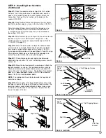
The operator arm will usually be attached to the vertical 
reinforcement member at roughly the same height as the top 
roller of the door. Attach the opener arm to the reinforcement 
as shown in Figures 18-B to 18-C. To prevent the top of the 
door from bending, the opener rail should be mounted no less 
than 2" and no greater than 5" from the face of the door with 
the door in the open position (FIG. 18-A). Additionally, when 
the door is closed, the portion of the operator arm attached to 
the door should be at angle of approximately 60 degrees from 
the vertical. 


FIG. 18-B (Doors with odd number of panels) 


FIG. 18-A 


FIG. 18-C (Doors with Angle Iron Reinforcement Bracket 
and Stile in Center of Door) 


Opener Arm Attachment To Horizontal Angle Or Strut 


 Opener Arm 

  Punched 
  Angle 

Horizontal Angle 
Or Strut 

Punched

Angle

   Horizontal

Angle

Or Strut


Opener Arm 

  Lock These Nuts 
  Together Securely 

Opener Arm Attachment To Vertical Angle


   Horizontal
   Punched 

  Angle

3/8” x 
1-1/2” 
Hex Bolt 


   Opener Arm

Vertical 
Punched
Angle 

3/8” 
Hex Nut

 Mounting Surface
 Of Door

  Vertical Punched
  Angle 

   Lock These 
   Nuts Together 
   Securely 


    Opener 
    Arm 


 Leave 
 Clearance 

Opener Rail Mounting Distance 

 Ceiling 

 Opener Rail 

Horizontal Track 


  Keep Clearance at 2” – 5”


60


degrees 

Summary of Contents for Avante AV

Page 1: ...or door surface Size Homeowners Should Retain This Booklet for Future Reference This Manual Contains Important Safety Information CONSUMER HOTLINE 1 800 2CLOPAY 1 800 225 6729 Hours of Operation ET Mo...

Page 2: ...e pursuant to the terms of this limited warranty In addition we will repair or replace at our option any garage door section section component that is defective in material or workmanship WE WILL NOT...

Page 3: ...ed and installed This will take approximately 5 hours To avoid damage to the door you must reinforce the top section of the door in order to provide a strengthened mounting point for attachment of an...

Page 4: ...e track Track installations must use sway braces on the rear track hangers to prevent sideways movement If the tracks are not firmly stabilized they might spread allowing the door to fall and cause se...

Page 5: ...uirement is shown in Table 3 A at right Low Headroom If you have restricted headroom several remedies are available See Table 3 B for various options NOTE Installation of the various Low Headroom Opti...

Page 6: ...ving or falling once the springs are removed Step 4 2 Detach the cable at both ends Disassemble and remove the springs and cable completely from the door NOTE Wood blocks should be placed underneath t...

Page 7: ...the same height as the headroom required If you have just removed an old door the jambs should be inspected for the condition of the wood If the wood is rotten it should be replaced now The jambs shou...

Page 8: ...ion Spring System Only torsion springs are available on the Avante door While the other spring setups are not representative of Avante doors they are shown here to help determine the type of spring se...

Page 9: ...x 6 6 8 0 H Double Car Doors 16 W x 6 6 8 0 H 5 Section Doors 4 Section Doors Single Car Doors 8 10 W x 6 6 7 0 H Double Car Doors 16 W x 6 6 7 0 H Single Car Doors 8 10 W x 6 6 8 0 H Double Car Doors...

Page 10: ...ead Bolt 1 1 or 2 1 2 3 8 Flange Nut 3 8 16 x 3 4 Carriage Bolt 3 8 x 3 4 Hex Head Bolt Doors With One Spring Doors With Two Springs Doors With One Spring Doors With Two Springs 2 0 0 2 All Doors All...

Page 11: ...bottom bracket Secure with cotter pin Fig 7 B for standard door Fig 7 C for low headroom door Step 7 4 Attach the bottom brackets with 5 1 4 x 3 4 red colored self drilling screws to the bottom corne...

Page 12: ...le Door Width Glazing Type Up to 11 2 11 4 to 12 2 12 4 to 14 2 14 4 to 16 2 16 4 to 20 2 Acrylic OR 1 8 Tempered None None G G H 1 2 Insulated OR 1 4 Tempered None G G H G 1 1 1 4 x 1 1 4 Aluminum An...

Page 13: ...utside handle Line up with outside edges of Center Stile of 2nd section when locating vertical outside handle Line up with top edge of bottom rail of bottom section when locating horizontal outside ha...

Page 14: ...14 Template and Handle Hole Locations Template and hole locations for bottom horizontal handle Template and hole locations for 2nd section vertical handle Bottom of Door Bottom Section 2nd Section...

Page 15: ...Allen wrench Fig 8 C 2nd Section to be installed at the completion of step 9 5 Step 8 5 Using the template provided on page 13 mark and drill 2 9 64 dia holes through the front wall of center stile cl...

Page 16: ...e illustration FIG 9 C Attach a number 2 hinge to each end at the top edge using 1 4 x3 4 self drilling screws Remember that the number is stamped on the side of the hinge that is to be attached to th...

Page 17: ...4 or higher number hinges on the end of the top edge and center hinges to all other stiles along the top edge Step 9 11 The reinforcing aluminum angle should now be attached to top rail with a 1 4 x3...

Page 18: ...2 Wide Doors FIG 10 B Required materials 1 18 21 or 24 and 1 48 length of iron 6 x self tapping screws Odd Stiles over 12 Wide Doors FIG 10 C Required materials 1 18 21 or 24 length of iron and 1 48 a...

Page 19: ...oper bolt placement NOTE If additional adjustment is required horizontal slots in flag brackets can be used for attachment to vertical track Step 11 3 Place the track over the rollers on the door Move...

Page 20: ...of the horizontal angle to the top of the flag bracket with a 3 8 x 3 4 carriage bolt and 3 8 hex nut Use the top set of slots for 15 radius track the middle set of slots for 12 radius track and the...

Page 21: ...e slide bolts FIG 12 F At this time remove the 3 nails that were used to hold sections in place prior to installation of the track assembly Refer back to FIG 9 B STEP 13 Lock Installation If Included...

Page 22: ...ter of end bearing Use this measurement draw a line at the same height for shaft location and mount 2 x 6 wood jambs in center of doorway FIG 15 C Important The wood anchor pad must be made of a Grade...

Page 23: ...bracket secures the springs to the wall You must fasten securely with red colored fasteners Never remove spring anchor bracket when springs are wound Step 15 6 With an assistant lift the complete tor...

Page 24: ...g Turns 6 0 6 75 6 3 7 00 6 6 7 25 6 9 7 50 7 0 7 75 7 3 8 00 7 6 8 25 7 9 8 50 8 0 8 75 For doors over 8 0 see the spring label Step 15 11 Unlock the door slowly raise the door and prop it about half...

Page 25: ...irection Step 16 3 Slip onto one section of solid steel shaft the coupler a spring anchor bracket left winding torsion spring black winding cone and the black cable drum The set screws on the drums fa...

Page 26: ...the spring tube the red winding cone on the left end the steel center bearing center bearing plate and the black winding cone torsion spring on the right end FIG 17 A Spring anchor bracket secures the...

Page 27: ...ally be attached to the vertical reinforcement member at roughly the same height as the top roller of the door Attach the opener arm to the reinforcement as shown in Figures 18 B to 18 C To prevent th...

Page 28: ...int Repair Should your door s paint finish become damaged exposing the bare metal it will become necessary to repair The damaged area should be lightly sanded with a medium to fine sandpaper making su...

Page 29: ...re frequently if road salt accumulates in a winter climate The door should be wiped down with a mild household detergent and rinsed with clean water NOTE Be sure to clean behind stop molding on the si...

Reviews: