PM4/8/12/16 & PM4/8-SA Installation and User Guide v1.1
46
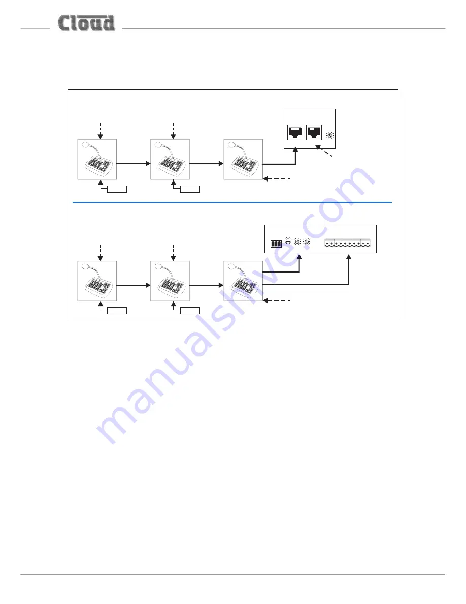
All other PMs on the network must be powered individually by external PSUs. DC
power is only connected internally at the CAN PORT OUT socket, so the ‘daisy-
chain’ data/audio connection cannot be used to pass power between PM units.
(with Digital Paging Interface)
M ix er
M IC INPUT
PAG ING ACCESS
M ix er
+ 1 2 V
Z 1
Z 2
Z 3
Z 4
Z 5
Z 6
Z 7
Z 8
0 V
LF
H F
G AIN (dB)
5 0
1
2
3
1 0
+
-
-
+
(with Analogue Paging Interface)
IN
OUT
OUT
Term ination OF F
CAT-5
CAT-5
CAT-5
CAT-5
CAT-5
(INCLUDING DC POWER FROM MIXER)
(INCLUDING DC POWER FROM MIXER)
Term ination
OF F
Term ination ON
IN
OUT
Term ination
ON
IN
OUT
AUDIO OUT
ZONE ACCESS CONTROL
Term ination
OF F
IN
OUT
Term ination
ON
PSU
PSU
PSU
PSU
CDPM
GAIN (dB)
IN
THRU
-10
+10
Term ination ON
T
Terminations
PMs are shipped from the factory with the Digital Paging Interface termination ON.
This requires no alteration in single-PM systems, but in multiple-PM systems, only the
microphone at the ‘far end’ of the network may have its termination ON; all others
must have their terminations set OFF. See “Terminating the Digital Paging Interface”
on page 42 for details of how to set the termination.
In all systems, the Digital Paging Interface termination must be set ON in the host
mixer. Refer to the mixer documentation for details.
Using the analogue interface with multiple PMs
The ‘last’ mixer in the chain – that connected to the host mixer – may be connected to
the host via the analogue interface instead of the Digital Paging Interface, if the host mixer
is not equipped with the digital interface. Connect the PM in the same way as if it was the
only PM in the system, using separate audio and control cables. See “Connecting the PM
to a mixer via the analogue interface” on page 28 for full details.
Communication between PMs will be via the digital interface, and between the last
PM (effectively the whole network) and the host will be via the analogue interface.


