background image

USER MANUAL : 


DOCUMENT NAME

To  switch  between  the  Diagnostic  Mode  and  Command  Mode,  simply  press 

from  the  Diagnostic  Mode  to  Command  Mode  can  take  several  seconds  depending  on  what  the 
executing. Command Mode is shown with the [COMMAND MODE] text in the communications block.
responses will be displayed in the 'Communications' block. This information can be cleared by right clicking in this box and 

selecting the 'Clear Screen' option. 

The logger must be in 'Command Mode' before any of the settings changes or other instructions are a

command in Diagnostic Mode will cause the 
 

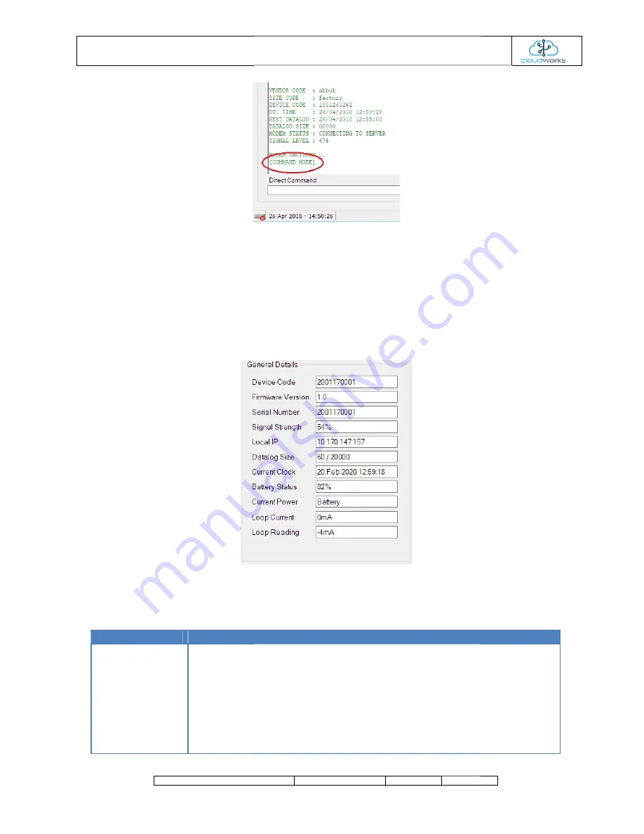
The information on this screen is ordered in various groups. The 'General Details' box holds information that is not alte

and is general information about the logger. This information consists of the following data:
 

Information 

 
Device Code 


Firmware Version 
 

Serial Number 


The Device Code assigned to this particular  
addressing  this  code.  This  code  is  unique  to  all   

manufacture. 
 
Firmware version of the software loaded on the 
 

Serial number of this 
 

MANUAL : CDS551 CIRRUS MODBUS LOGGER 

NAME 

CLASSIFICATION 

DATE 

PAGE


To  switch  between  the  Diagnostic  Mode  and  Command  Mode,  simply  press  the  'Command/Connect'  button.  Switching 

from  the  Diagnostic  Mode  to  Command  Mode  can  take  several  seconds  depending  on  what  the 
executing. Command Mode is shown with the [COMMAND MODE] text in the communications block.

nses will be displayed in the 'Communications' block. This information can be cleared by right clicking in this box and 

before any of the settings changes or other instructions are a

command in Diagnostic Mode will cause the logger to switch to Command Mode but that last instruction will 


The information on this screen is ordered in various groups. The 'General Details' box holds information that is not alte

. This information consists of the following data: 

Notes 

The Device Code assigned to this particular  logger. All communications are initiated by 
addressing  this  code.  This  code  is  unique  to  all    loggers  and  is  assigned  at  the  time  of 

Firmware version of the software loaded on the logger 

Serial number of this logger - assigned in the factory. 


PAGE 

Command/Connect'  button.  Switching 

from  the  Diagnostic  Mode  to  Command  Mode  can  take  several  seconds  depending  on  what  the  logger  is  currently 
executing. Command Mode is shown with the [COMMAND MODE] text in the communications block. All commands and 

nses will be displayed in the 'Communications' block. This information can be cleared by right clicking in this box and 

before any of the settings changes or other instructions are accepted

. Sending a 

to switch to Command Mode but that last instruction will fail. 

The information on this screen is ordered in various groups. The 'General Details' box holds information that is not alterable 

. All communications are initiated by 

s  and  is  assigned  at  the  time  of 

Summary of Contents for CDS551

Page 1: ...r User Manual User 1 December 2020 V1 0 Draft Confidential CDS551 Cirrus Modbus Logger User Manual docx This document contains information relating to the rights of Cape Digital Solutions The confiden...

Page 2: ...DOCUMENT NAME Issue Date V01 13 July 2021 MANUAL CDS551 CIRRUS MODBUS LOGGER NAME CLASSIFICATION DATE PAGE AMENDMENT HISTORY Amendment Details Amended By Compile document Alex Romanov PAGE Amended By...

Page 3: ...24V loop power generator 1 7 3 Using the RS485 Modbus interface 1 8 Sim card and battery installation 1 9 Installation considerations 2 Logger Setup 2 1 Setup via Bluetooth Configure 2 2 Setup via Rem...

Page 4: ...t software CloudWorks is allow clients to manage their own networks and data There are no monthly charges for collecting and hosting data as the client can provide this service themselves GPRS EDGE LT...

Page 5: ...ME CLASSIFICATION DATE PAGE Onboard 24V 30mA power generator The Cirrus Modbus logger can generate a stable 24V output at a maximum of 30mA allowing for the powering of an external piece of equipment...

Page 6: ...this mode the logger can be continuously connected to the server allowing for the streaming Modbus logger uses standard D Cell alkaline batteries that will last several years In this mode the logger...

Page 7: ...etooth is ready to receive an incoming connection Solid light indicates and active connection Logger is in Command Mode normally accompanied by an active Bluetooth connection Logger is currently initi...

Page 8: ...a positive input D 8 Modbus RS485 Data negative input D 9 Isolated ground for Modbus RS485 input 10 Earthing connection Modbus RS485 input transient voltage protection MANUAL CDS551 CIRRUS MODBUS LOGG...

Page 9: ...aline batteries means that the logger can be put e is solar power available the logger will remain online with the server Should the solar power fail the logger will automatically switch to battery mo...

Page 10: ...N DATE PAGE he loop should only be powered each time the device needs to be read oop Power mode Example configuration of the generator supplying power to a loop powered device Using the RS485 Modbus i...

Page 11: ...atermaster flow meter Watermaster Modbus Setup MANUAL CDS551 CIRRUS MODBUS LOGGER NAME CLASSIFICATION DATE PAGE Example configuration for connection to an Aquamaster 3 4 flow meter Modbus Setup 19200...

Page 12: ...n for connection Cloudworks BGT Sensor Modbus Setup MANUAL CDS551 CIRRUS MODBUS LOGGER NAME CLASSIFICATION DATE PAGE Example configuration for connection Cloudworks Hydrostatic BGT sensor Modbus Setup...

Page 13: ...o cover the sim card 5 Slide the cover plate forward again to lock into the base 1 2 MANUAL CDS551 CIRRUS MODBUS LOGGER NAME CLASSIFICATION DATE PAGE installation oSIM and is installed as follows Slid...

Page 14: ...CLASSIFICATION DATE PAGE Battery Installation Installation considerations Modbus logger is environmentally rated to IP68 max1 2m In order to achieve this it is critical that any cables entering the l...

Page 15: ...SSIFICATION DATE PAGE This logger can be configured using 3 different methods interface Remotely when a logger is powered and is currently online Via a scripting method for battery operated loggers th...

Page 16: ...h for the available remote devices in the immediate Once the search has been completed a list of all the available devices will be displayed Should the device you are looking the Refresh button to sta...

Page 17: ...ll initiate a connection immediately nce the Bluetooth connection has been established Cloudworks will automatically activate the correct configuration needed for each device type This device will imm...

Page 18: ...ith the COMMAND MODE text in the communications block nses will be displayed in the Communications block This information can be cleared by right clicking in this box and before any of the settings ch...

Page 19: ...gger load Bluetooth communications active It would normally indicate lower than the recorded battery status in the datalog which is read while the essentially idle An indicator as to how this logger i...

Page 20: ...is associated with a specific logger Each database and ssigned to it Data is matched between these systems using that code This code is also used to separate communications between different vendors...

Page 21: ...ard have a pincode activated it will request the pincode when the modem powers up and starts connecting to the network If the pincode field here is the logger will offer this code to the network allow...

Page 22: ...Start Time timer will be started Should the connection to the server take longer than this preset time the connection will be aborted and the logger will be put back to sleep For powered loggers the...

Page 23: ...Power Threshold voltage This should only under special circumstances be adjusted from 4 75V ch logger is an onboard 24V 30mA power generator The Cumulus Logger can generate a stable 24V output at allo...

Page 24: ...in Command Mode pressing this button will send a command to clear the onboard datalog Forces the logger to wake up and connect to the server This will also force a battery logger to connect to the ser...

Page 25: ...t 4mA Point Change the source current on the interface to an accurate 20mA Dropdown the Calibrate Loop menu and select the Set 20mA Point loop current to any random value between 4mA and 20mA Press th...

Page 26: ...urther configurations when a logger is in battery mode and asleep disconnecting the battery will not cycle the device A battery logger in sleep mode can remain powered for up to 5 minutes before the o...

Page 27: ...ters are the same as when you configure via the Bluetooth setup option Again d commands are sent to the device only after the parameter setup field has been left What this means is that while adjustin...

Page 28: ...t server so will go offline here preventing you from making any further changes The Remote Configure screen has one further tool available in its arsenal and that is the Send Test SMS function The pur...

Page 29: ...he Bluetooth setup option with one or two minor All the parameter fields are empty at this point To create a script simply enter the new values for the parameters you wish The script will only be gene...

Page 30: ...d to be executed Listed also is the response to each command for diagnostic purposes You can read back the current script to determine its status at any point by pressing the Read Script button he dat...

Reviews: