Page 12-22
12
G
Test Procedure 11, Continued:
1. Place the neutral lock-out cam in the SERVICE position, put the forward and reverse lever in the NEU-
TRAL position, and chock the wheels.
2. Remove the plug wire from the spark plug. Using an ignition spark gap test tool (Thexton 404® or
equivalent), check for correct spark (Figure 12-29, Page 12-21).
2.1. Adjust the tester probes to approximately to 18,000 volts (18 Kv) setting. Connect the tester to the
spark plug wire, and connect the alligator clip to the frame.
2.2. Turn the key switch to the ON position and crank the engine by depressing the accelerator. There
should be a strong blue spark between the probes of the spark gap tester. If there is no spark, or
if the spark is a faint yellow or white color, test components of the ignition circuit.
3. If the spark gap tester tool indicates a strong blue spark, it is possible the spark plug has failed inter-
nally. Replace the spark plug with a new part and test the engine for proper operation.
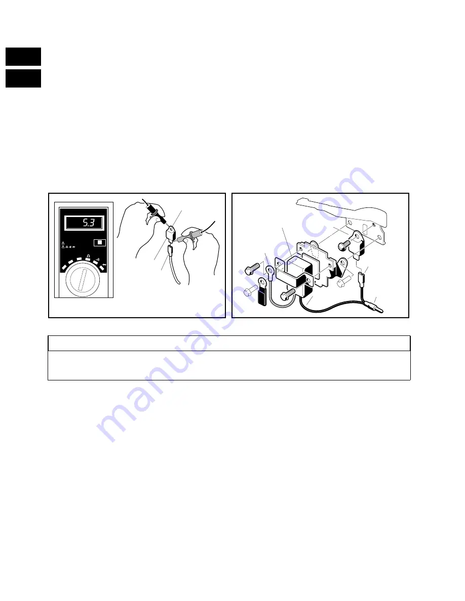
Test Procedure 12 - Igniter (Vehicles before AG9624-502638):
1. Place the neutral lock-out cam in the SERVICE position, put the forward and reverse lever in the NEU-
TRAL position, and chock the wheels.
2. Using a multimeter set on ohms (
Ω
), place the red (+) probe on the terminal. Place the black (-) probe
on the case. The reading should be between 2 - 6 ohms (
Ω
). If the reading is not correct, replace the
igniter (Figure 12-30).
3. The first test will find 90% of the bad igniters. Some igniters may bench test okay but fail under a load
due to heat while operating. Another method of testing is to replace the igniter and then run the engine.
If the engine runs properly, keep the new igniter in the circuit.
Test Procedure 13 - RPM Limiter (Figure 12-31):
1. Place the neutral lock-out cam in the SERVICE position, put the forward and reverse lever in the NEU-
TRAL position, and chock the wheels.
2. Disconnect the female slip-on connector from the igniter (on some vehicles the igniter is located in the
ignition coil and on other vehicles the igniter is behind the RPM limiter, against the engine block). Dis-
connect the bullet terminal. Using a multimeter set on ohms (
Ω
), place the red (+) probe on the brown
ground wire and place the black (-) probe on the black wire male bullet connector. The reading should
be between 4.5 to 7 ohms (
Ω
). If the reading is not correct, replace the RPM Limiter.
FIGURE 12-30
FIGURE 12-31
• TO TEST IGNITERS ON VEHICLES WITH SERIAL NUMBERS GREATER THAN AG9624-502638,
SEE IGNITION COIL TEST PROCEDURE 14.
OFF
DC V
DATA HOLD
AC V
AC/DC 500V MAX
250V MAX
IGNITER
SLIP-ON
CONNECTOR
CASE
VEHICLES
BEFORE 9624-502638
;;
;;
;;
yy
yy
yy
BROWN
WIRE
RPM LIMITER
IGNITER
BLACK WIRE
FEMALE
SLIP-ON
MALE
BULLET
TERMINAL
VEHICLES
BEFORE 9624-502638
NOTE
Summary of Contents for 1996 DS Golf Car Gasoline
Page 2: ......
Page 28: ...Page 3 14 3 E G...
Page 38: ...Page 4 10 4 E G...
Page 76: ...Page 6 30 6 E G...
Page 110: ...Page 8 26 8 E G...
Page 136: ...Page 11 6 11 G...
Page 268: ...Page 15 4 15 G...
Page 286: ......
Page 316: ...Page 18 6 18 G...
Page 332: ...Page 19 16 19A E...
Page 350: ...Page 19 34 19A E...
Page 444: ......
Page 451: ...Page 21 59 E 21B FIGURE 21 85 2 4 5 7 8 1 9 6 5 4 3...
Page 452: ...Page 21 60 21A E...
Page 472: ...Page 22 20 22 E...
Page 524: ...Page 23 52 23A E...
Page 543: ......
Page 544: ...Golf Cars Club Car Inc P O Box 204658 Augusta GA 30917 4658...


