Page 20-35
E
20A
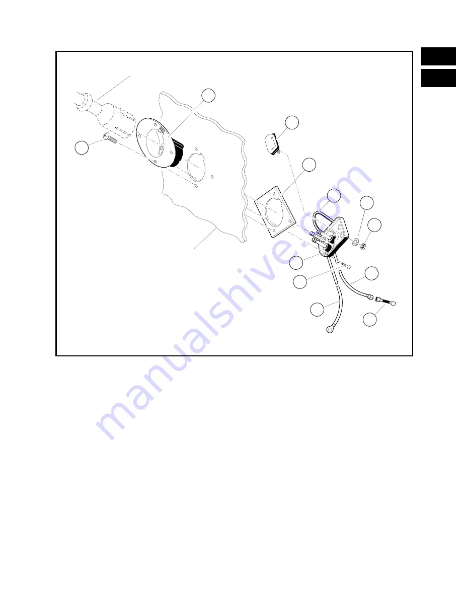
Removing the Receptacle
1. Remove the 10 gauge red wire (4) from the positive post of battery No. 1, and then pull the 10 gauge
red wire to the receptacle (2) (Figure 20-17).
2. Locate the 1/4” “quick disconnect” terminal on the 10 gauge grey wire from the charger receptacle. Dis-
connect the 10 gauge grey wire (3) at this terminal, leaving the sense lead fuse (1) attached to the grey
wire from the on-board computer (Figure 20-17).
3. Remove the 10 gauge black wire (5) from the charger receptacle using a ratchet and a 3/8” socket.
4. Use a phillips screwdriver to remove the four screws (9) from the bezel (7), and the three screws (12)
from receptacle (2).
Installing a New Receptacle (Figure 20-17)
1. Install the bezel (7) with four screws (9) through the bezel and body and into the receptacle backing
plate (8). Torque screws to 9-13 in.lbs. (1.0/1.5 N-m) (Figure 20-17).
2. Insert the fuse and receptacle assembly (2) through the receptacle backing plate and into the bezel as
shown, then install the three mounting screws (12).
3. Thread the 10 gauge red wire (4) through the tie wraps on the front body support and attach the con-
nector to the positive post of battery No. 1 (See Figure 23-20, Page 23-29).
FIGURE 20-17
4
1
2
3
5
6
7
8
9
11
10
D.C. CORDSET
SEAT SUPPORT
FRONT PANEL
12
Summary of Contents for 1996 DS Golf Car Gasoline
Page 2: ......
Page 28: ...Page 3 14 3 E G...
Page 38: ...Page 4 10 4 E G...
Page 76: ...Page 6 30 6 E G...
Page 110: ...Page 8 26 8 E G...
Page 136: ...Page 11 6 11 G...
Page 268: ...Page 15 4 15 G...
Page 286: ......
Page 316: ...Page 18 6 18 G...
Page 332: ...Page 19 16 19A E...
Page 350: ...Page 19 34 19A E...
Page 444: ......
Page 451: ...Page 21 59 E 21B FIGURE 21 85 2 4 5 7 8 1 9 6 5 4 3...
Page 452: ...Page 21 60 21A E...
Page 472: ...Page 22 20 22 E...
Page 524: ...Page 23 52 23A E...
Page 543: ......
Page 544: ...Golf Cars Club Car Inc P O Box 204658 Augusta GA 30917 4658...


