ELECTRICAL COMPONENTS
Electronics Module Cover
Page 12-6
2005 Precedent IQ System Electric Golf Car Maintenance and Service Manual
12
TOW/RUN SWITCH
See General Warnings, Section 1, Page 1-1.
Testing the Tow/Run Switch
See Test Procedure 6, Section 11, Page 11-19.
Tow/Run Switch Removal
1. Disconnect the battery cables as instructed.
See WARNING “To avoid unintentionally starting...” in
General Warnings, Section 1, Page 1-2.
2. Remove the electronics module cover.
See Electronics Module Cover Removal on page 12-5.
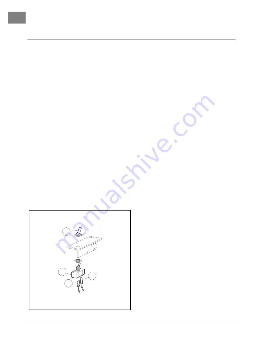
3. Remove Tow/Run switch boot/hex nut (1)
(Figure 12-6, Page 12-6).
4. Remove Tow/Run switch (2) from bracket.
5. Disconnect the two wires (3) and remove switch.
Tow/Run Switch Installation
1. Installation is reverse of removal. Make sure flat on switch is aligned with the flat on bracket. Tighten Tow/
Run switch boot/hex nut (1) to 16 in-lb (1.8 N·m)
(Figure 12-6, Page 12-6).
2. Install the electronics module cover.
See Electronics Module Cover Installation on page 12-5.
3. Place the Tow/Run switch in the TOW position and connect the battery cables, positive (+) cable first.
Tighten battery terminals to 110 in-lb (12.4 N·m) and coat terminals with Battery Terminal Protector
Spray (CCI P/N 1014305) to minimize corrosion.
Figure 12-6 Tow/Run Switch
1
2
3
3
PINK
BLUE


