ELECTRICAL COMPONENTS
Electronics Module Cover
Page 12-8
2005 Precedent IQ System Electric Golf Car Maintenance and Service Manual
12
REVERSE BUZZER
See General Warnings, Section 1, Page 1-1.
Testing the Reverse Buzzer
See Test Procedure 16, Section 11, Page 11-37.
Reverse Buzzer Removal
1. Disconnect the battery cables as instructed.
See WARNING “To avoid unintentionally starting...” in
General Warnings, Section 1, Page 1-2.
2. Remove instrument panel.
See step 2 of Key Switch Removal on page 12-1.
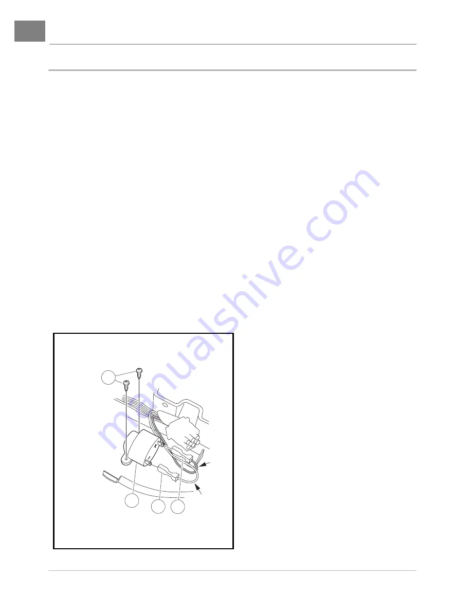
3. Disconnect the 18-gauge pink and orange/white wires from reverse buzzer.
4. Remove the two screws from the reverse buzzer. Remove the reverse buzzer from the dash panel.
Reverse Buzzer Installation
1. Install the reverse buzzer in the reverse order of removal. Pink wire must be connected to the positive
terminal. Tighten screws to 4 in-lb (0.45 N·m).
2. Place the Tow/Run switch in the TOW position and connect the battery cables, positive (+) cable first.
Tighten battery terminals to 110 in-lb (12.4 N·m) and coat terminals with Battery Terminal Protector
Spray (CCI P/N 1014305) to minimize corrosion.
Figure 12-8 Reverse Buzzer
REVERSE
BUZZER
VIEWED FROM
UNDERSIDE OF
INSTRUMENT
PANEL
3
2
1
4
PINK
ORANGE/
WHITE


