MOTOR (MODEL 5BC59JBS6365)
Motor Installation
2005 Precedent IQ System Electric Golf Car Maintenance and Service Manual
Page 15a-13
15A
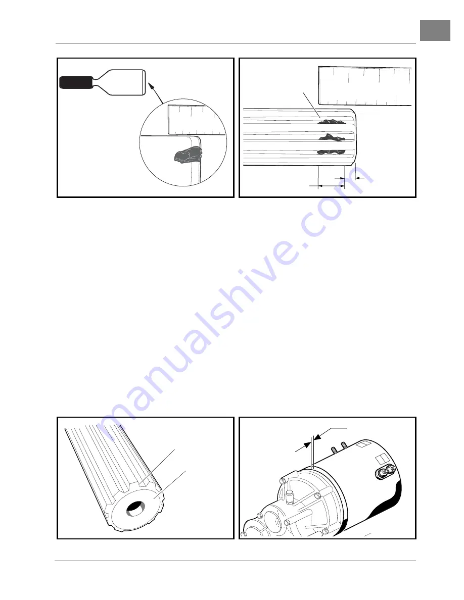
2.6. Check the chamfer and end of the input shaft to ensure these areas are completely clean of grease
as shown
(Figure 15a-16, Page 15a-13)
.
3. Install the molded bumper.
3.1. With the flat side toward the bottom of the coupling, install the molded bumper (30) into the motor
coupling
(Figure 15a-10, Page 15a-8)
.
See following NOTE.
NOTE: The motor coupling and the new molded bumper must be free of grease and debris.
3.2. Ensure that the installed bumper is seated at the bottom of the coupling.
4. Install motor on transaxle.
4.1. Slide the motor coupling onto the transaxle input shaft.
See following NOTE.
NOTE: The coupling will push any excess grease on the input shaft along the shaft toward the transaxle.
When the motor is pushed onto the input shaft, the motor adapter ring (1) will not bottom out
against the transaxle housing (Figure 15a-10, Page 15a-8). There will be approximately 1/16 inch
(1.6 mm) gap between the motor adapter ring and transaxle housing as shown (Figure 15a-17,
Page 15a-13).
Figure 15a-14 Grease on Putty Knife
Figure 15a-15 Application of grease to Input
Shaft Grooves
Figure 15a-16 Clean Chamfer and Input Shaft End
Figure 15a-17 Gap at Motor and Transaxle
1
2
1/2
mm
inch
1
2
3
1
1/2
mm
inch
GREASE
1/8 INCH
(3.1 MM)
3/8 INCH (9.5 MM)
SHAFT END
CHAMFER
1/16 Inch (1.6 mm)


