EXPORT POWERDRIVE BATTERY CHARGER (EXTERNAL)
Charger Installation and Operation
2008 Export Battery Charger Maintenance and Service Manual
Page 3-13
3
and plug terminals should be cleaned with a good electrical contact cleaner. The plug should then be inserted
and removed several times to ensure ease of insertion, ease of removal, and good electrical contact.
See
Charger Receptacle in Section 12 of the appropriate maintenance and service manual for receptacle
removal and installation. See also DC Cord Removal on page 3-30. See following NOTE.
NOTE:
If the warning tag has been damaged or removed from the DC cord, have it replaced immediately.
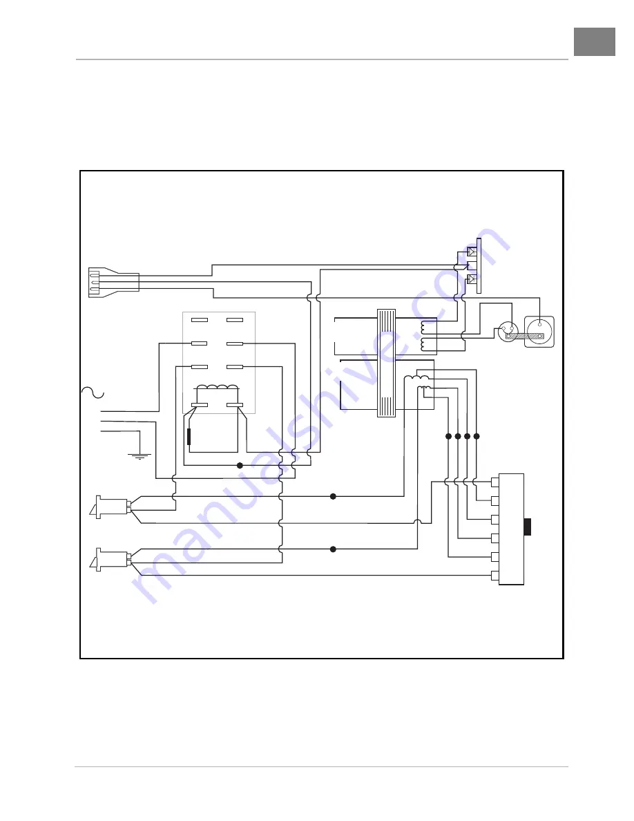
Figure 3-11 PowerDrive Export Charger Wiring Diagram
BLACK
BLACK (6)
DC CORDSET
RED
RED
BLUE
BLACK
BLACK
BLACK
AC CIRCUIT
BREAKERS
AC CORD
GRN/YEL
TA
N
TA
N
DIODES WITH
HEATSINK
AMMETER
TRANSFORMER
RELAY
PRIMARY
COIL
SECONDARY
COIL
RED
BLUE
9
7
6
4
CASE
GROUND
VOLTAGE
SUPPRESSOR
RED
RED
BLUE
BROWN
BLUE
BLUE
BLUE
BR
O
W
N
BLACK
BLACK
BLACK
BLACK
BLACK
BLACK(1)
BLACK(1)
BLACK
BLA
C
K
BLA
CK
BLACK
BLACK
BLACK (1)
TAN (1)
TAN (6)
T
A
N (1)
T
A
N (6)
T
A
N (5)
T
A
N (4)
T
A
N (3)
T
A
N (2)
BLA
C
K
BLA
C
K
BLA
C
K
BLA
C
K
BLACK
BLACK
BLACK
BLK
BLK
BLACK (6)
A
B
FUSE
1
2
3
4
5
6
TERMINAL #
A
C
V
O
LT
A
G
E SELECT
OR SWITCH


