GASOLINE ENGINE, MUFFLER, FUEL SYSTEM,
AND CLUTCHES
Clutches
15
2.
Remove the top air filter hose from the filter canister.
3.
Remove the clutch outer cover.
See Clutch Outer Cover Removal on page 15-37.
4.
Remove the drive belt as instructed.
See Drive Belt Removal on page 15-30.
5.
Remove the bolt and washer from the center of the clutch and discard bolt.
6.
Remove the driven clutch.
See following CAUTION.
CAUTION
• Do not hit or tap the clutch with a hammer. Do not pry the clutch. These actions will damage the clutch.
Driven Clutch Disassembly
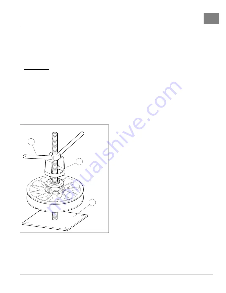
The following service tools are required to disassemble and assemble the driven clutch. They are available from
a service parts representative:
• Spring compression base (CC P/N 102603501)
• Spring compression collar (CC P/N 102605201)
• Spring compression nut (CC P/N 102606101)
1
3
2
2174
Figure 15-29
Driven Clutch Service Tools
1.
Place the driven clutch onto the Spring compression base (CC P/N 102603501) (1)
2.
Place the Spring compression collar (CC P/N 102605201) (2) onto the driven clutch.
3.
Thread the Spring compression nut (CC P/N 102606101) (3) down onto the threaded post enough to release
the pressure on the snap ring.
2016 Carryall 1500/1700 and XRT 1550 Maintenance and Service Manual
Page 15-35
Summary of Contents for Carryall 1500 2016
Page 2: ......
Page 432: ...NOTES...
Page 433: ...NOTES...
Page 434: ...NOTES...
Page 435: ......
Page 436: ......


