17
Half Shafts
DRIVETRAIN COMPONENTS
1895
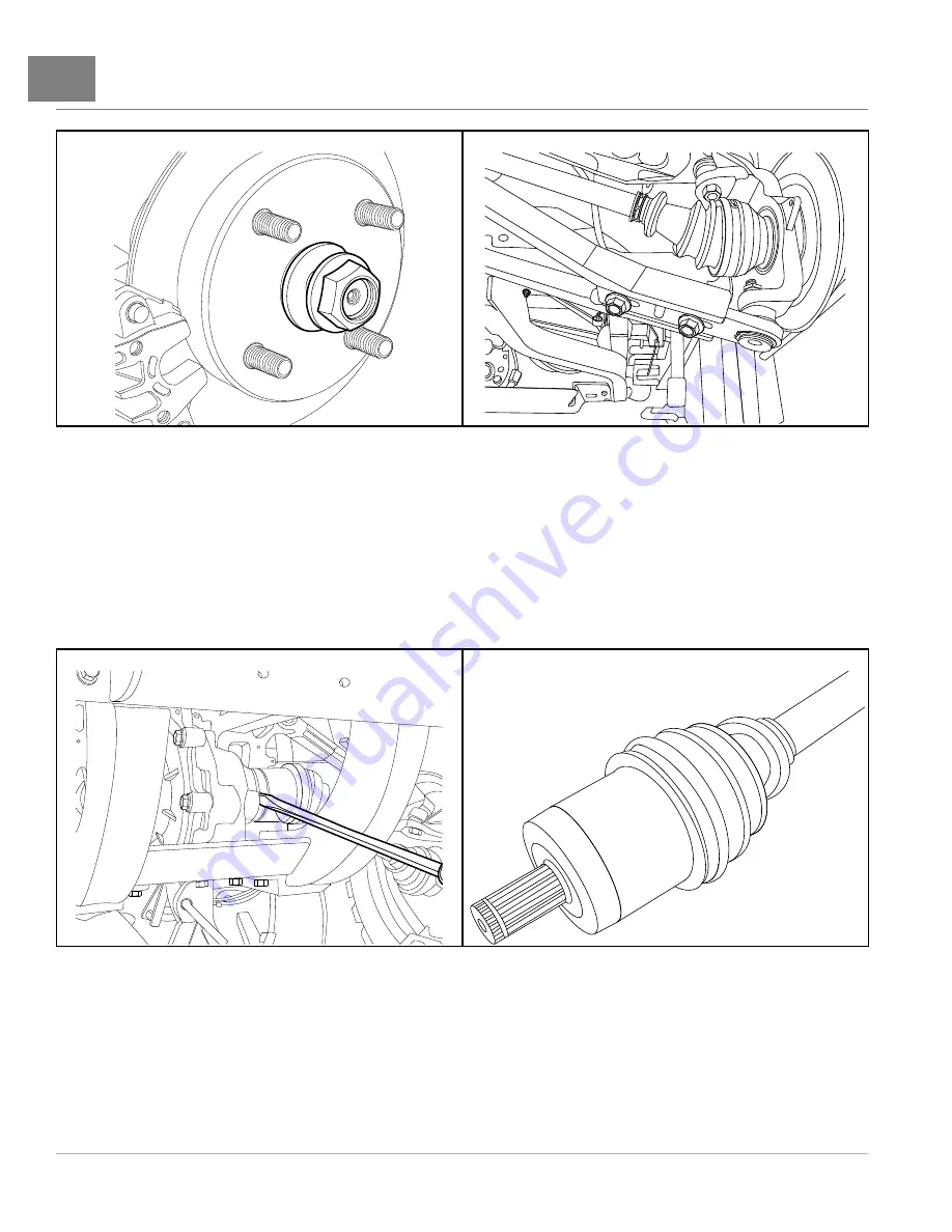
Figure 17-1
Axle Spindle Nut And Washer
2193
Figure 17-2
Camber Adjustment Bar
13.
Separate the half shaft hub from the differential and remove the half shaft
See
following NOTE.
NOTE:
Use a 5/16-inch wide flat blade screwdriver to separate the half shaft hub and differential.
The hub end of the half shaft has a round compression ring and groove. The compression ring mates with a
groove inside the differential
14.
Repeat steps for the remaining half shaft.
2194
Figure 17-3
Separate Half Shaft from Differential
2195
Figure 17-4
Compression Ring on Spline
HALF SHAFT INSTALLATION
Half shafts are assembled with CV joints and are available only as a complete assembly. If a half shaft is replaced
because of wear, the manufacturer recommends that both half shafts be replaced.
1.
Apply a light coat of anti-seize compound to each end of the half shaft splines
.
Page 17-2
2016 Carryall 1500/1700 and XRT 1550 Maintenance and Service Manual
Summary of Contents for Carryall 1500 2016
Page 2: ......
Page 432: ...NOTES...
Page 433: ...NOTES...
Page 434: ...NOTES...
Page 435: ......
Page 436: ......


