7
Rack and Pinion
STEERING AND FRONT SUSPENSION
RACK AND PINION INSPECTION
Look for obvious damage to the chassis, where the rack and pinion is mounted, and the rack and pinion housing.
Particularly check the housing for broken mounting points.
Compare the toe-in against the specification.
See Toe-in Measurement on page 7-11.
If obvious visible damage is found, such as a bent tie rod, check the steering gear for abnormal free-play, noise, binding
or clunking while it is under a load. With the steering system fully assembled and all four tires on the ground/floor,
turn the steering wheel from stop to stop. While turning, feel for any binding, clunking or tight/loose spots. Listen for
unusual noises. Replace the rack and pinion as an assembly if any is found.
In the event of an known impact and obvious visible damage is not found in the method described above, disconnect
the tie rods and/or drag links from the spindles. Turn the steering wheel from stop to stop. While turning, feel for any
binding or tight/loose spots. Listen for unusual noises. Replace the rack and pinion as an assembly if any is found.
RACK AND PINION REMOVAL
1.
Lift and support the front of vehicle and remove the wheels.
See Lifting The Vehicle on page 3-9.
2.
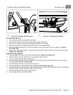
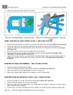
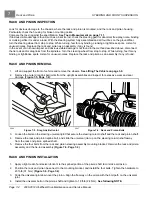
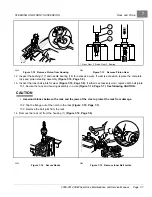
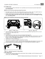
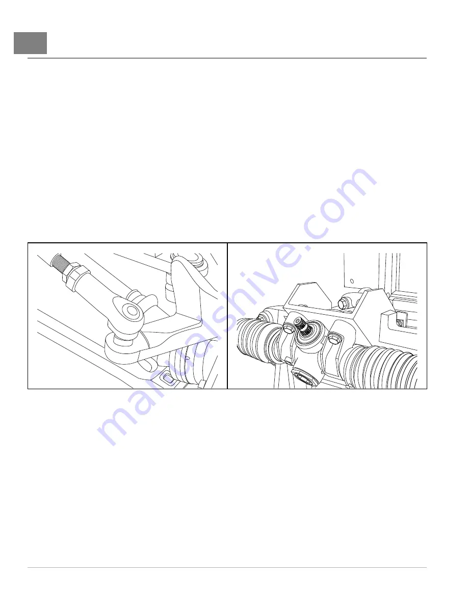
Remove the outer drag link ball joints from the upright assemblies and inspect for excessive wear and seal
damage
2046
Figure 7-5
Drag Link Ball Joint
2047
Figure 7-6
Rack and Pinion Bolts
3.
Loosen the bolts on the steering universal joint that secure the steering column shaft and the rack and pinion shaft.
4.
Remove the rack and pinion spline bolt, and slide the universal joint up on the steering column shaft away
from the rack and pinion splined shaft.
5.
Remove the four bolts from the rack and pinion steering assembly mounting bracket. Remove the rack and pinion
assembly and the tie-rod assembly
.
RACK AND PINION INSTALLATION
1.
Apply a light coat of anti-seize lubricant to the splined portion of the pinion shaft to minimize corrosion.
2.
Position the rack and pinion base next to the mounting bracket, and install the four bolts. Tighten the hardware to
23 ft-lb (31 N·m)
.
3.
Slide the universal joint down over the pinion. Align the flat-way on the pinion with the bolt path on the universal
joint.
4.
Install the universal bolt on the pinion shaft and tighten to 18 ft-lb (24 N·m).
See following NOTE.
Page 7-4
2008-2012 All-Wheel Drive Maintenance and Service Manual
Summary of Contents for Carryall 295 SE
Page 2: ......
Page 20: ......
Page 28: ......
Page 58: ......
Page 66: ......
Page 100: ......
Page 122: ......
Page 150: ......
Page 157: ......
Page 190: ......
Page 197: ......
Page 236: ......
Page 284: ......
Page 386: ......
Page 394: ......
Page 442: ......
Page 452: ......
Page 454: ......
Page 455: ......
Page 456: ......

