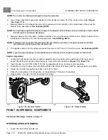
STEERING AND FRONT SUSPENSION
Front Suspension Components
7
2.
Lift and support the front of vehicle and remove the wheels.
See Lifting The Vehicle on page 3-9.
3.
Remove the front brake caliper.
See Front Brake Pad and Caliper Removal, Section 6, Page 6-6.
4.
Rest the brake caliper on the A-arm. Ensure that there is no strain on the brake hose.
See following WARNING.
WARNING
• Strain on the brake hose or the brake hose fittings can result in damage to the line or fittings and
cause a leak in the hydraulic system, diminished brake performance, or brake failure.
5.
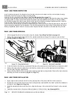
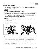
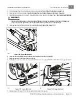
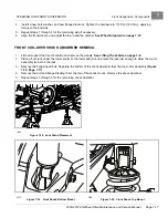
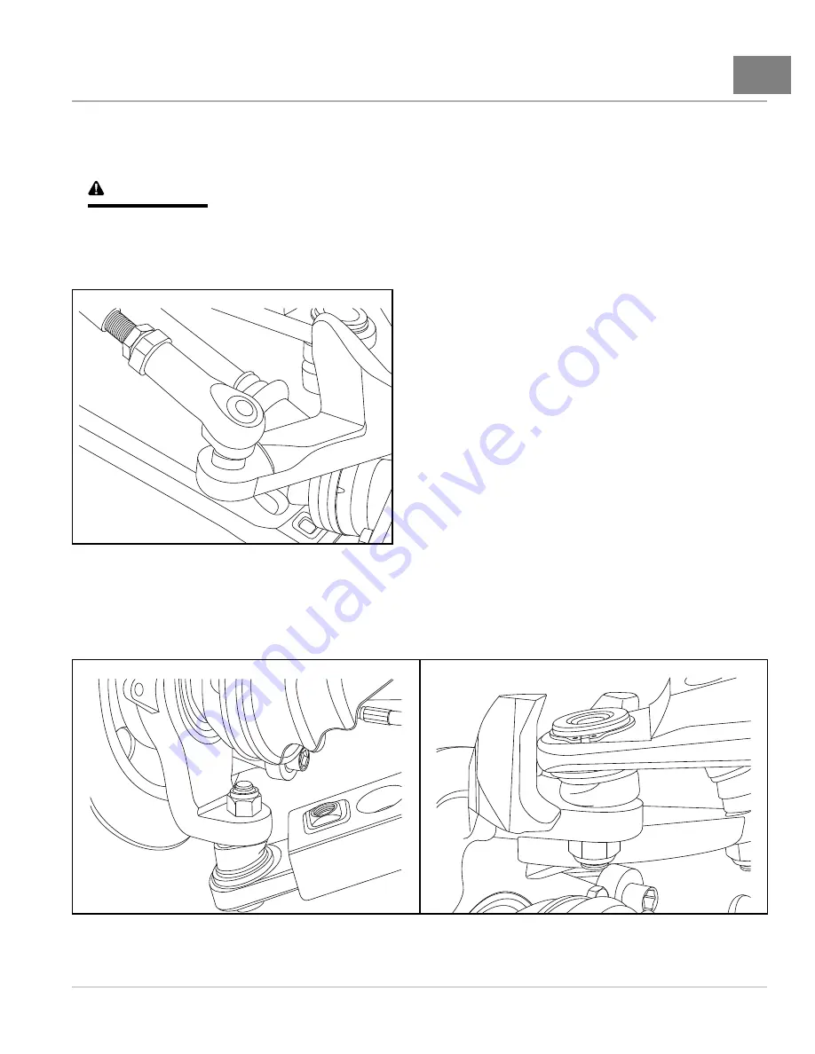
Remove the drag link ball joint from the upright assembly
2065
Figure 7-26
Drag Link Ball Joint
6.
Remove the axle spindle locknut that secures the wheel hub, disc, and upright.
7.
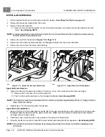
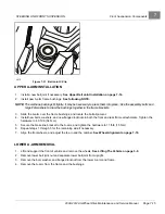
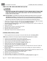
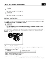
Remove the lower and upper ball joint locknut.
8.
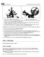
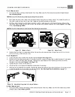
Swing the lower A-arm down, and separate the brake rotor and upright from the half-shaft and the upper ball joint.
2066
Figure 7-27
Lower Ball Joint
2067
Figure 7-28
Upper Ball Joint
9.
Repeat steps 5 through 10 for the remaining front wheel if necessary.
2008-2012 All-Wheel Drive Maintenance and Service Manual
Page 7-13
Summary of Contents for Carryall 295 SE
Page 2: ......
Page 20: ......
Page 28: ......
Page 58: ......
Page 66: ......
Page 100: ......
Page 122: ......
Page 150: ......
Page 157: ......
Page 190: ......
Page 197: ......
Page 236: ......
Page 284: ......
Page 386: ......
Page 394: ......
Page 442: ......
Page 452: ......
Page 454: ......
Page 455: ......
Page 456: ......

