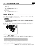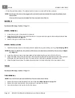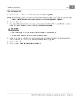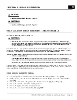
STEERING AND FRONT SUSPENSION
Front Suspension Components
7
4.
Install a new bolt, washer, and new flanged locknut. Tighten the hardware to 110 ft-lb (148 N·m), applying
torque to the bolt side.
5.
Repeat steps 1 through 4 for the remaining side if necessary.
6.
Align the front wheels, and adjust the toe-in and the camber.
See Wheel Alignment on page 7-10.
FRONT COIL-OVER SHOCK ABSORBER REMOVAL
1.
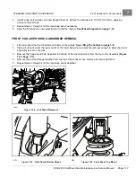
Lift and support the front of vehicle and remove the wheels.
See Lifting The Vehicle on page 3-9.
2.
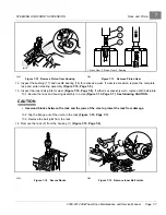
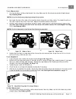
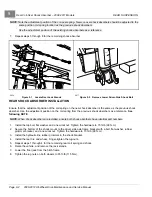
Place a floor jack under the lower A-arm at the lower ball joint, and raise the jack just enough to allow the A-arm
assembly to rest on the jack.
3.
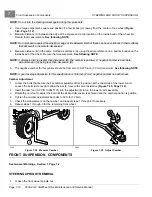
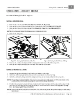
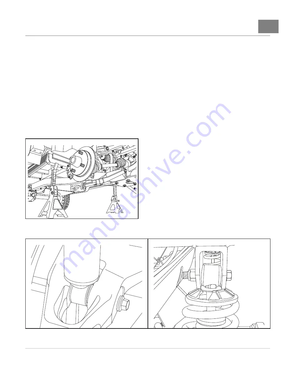
Remove the flange-head bolt. Separate the bottom of the shock absorber from the top A-arm assembly
.
4.
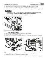
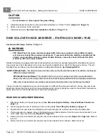
Remove the bolt and flanged locknut from the top of the shock mount. Remove the shock absorber.
5.
Repeat steps 3 through 6 for the remaining shock absorber.
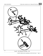
1890
Figure 7-34
Jack Stand Placement
2073
Figure 7-35
Front Shock Bottom Mount
2074
Figure 7-36
Front Shock Top Mount
2008-2012 All-Wheel Drive Maintenance and Service Manual
Page 7-17
Summary of Contents for Carryall 295 SE
Page 2: ......
Page 20: ......
Page 28: ......
Page 58: ......
Page 66: ......
Page 100: ......
Page 122: ......
Page 150: ......
Page 157: ......
Page 190: ......
Page 197: ......
Page 236: ......
Page 284: ......
Page 386: ......
Page 394: ......
Page 442: ......
Page 452: ......
Page 454: ......
Page 455: ......
Page 456: ......

