7
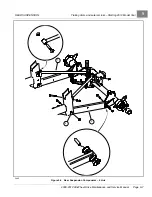
Front Suspension Components
STEERING AND FRONT SUSPENSION
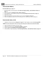
FRONT COIL-OVER SHOCK ABSORBER INSTALLATION
WARNING
• 2012 Model Year and newer vehicles equipped with 4-link rear suspension have front coil-over shocks
with spring rates that differ from previous shocks. To prevent altering the stability or handling of the
vehicle, never use these shocks on older models; likewise, never use shocks intended for older
models on 2012 and newer vehicles.
NOTE: 2008-2011 Models:
The standard-duty and heavy-duty suspensions used the same front coil-over shocks.
2012 Model Year and Newer:
The standard-duty front coil-over springs and shocks are painted black.
Heavy-duty front coil-over springs and shocks have shock housings painted black and springs painted silver.
When front shock absorbers are installed, ensure both shock absorbers have identical part numbers.
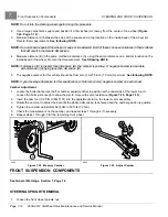
1.
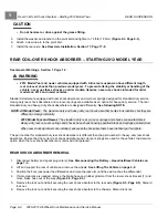
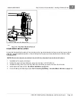
Install the top of the shock mount on the vehicle frame with a bolt and flange-head locknut. Tighten the hardware
to 62 ft-lb (84 N·m)
See previous WARNING and NOTES.
2.
Install the bottom of the shock mount on the upper A-arm with a new flange-head bolt. Tighten the hardware to 62
ft-lb (84 N·m)
.
3.
Remove the floor jack.
4.
Install the front tire and wheel. Finger-tighten the lug nuts.
5.
Raise the vehicle, and remove the jack stands.
6.
Tighten the lug nuts to 87 ft-lb (118 N·m).
7.
Repeat steps 1 through 6 for the remaining shock absorber.
STEERING UPRIGHT INSTALLATION
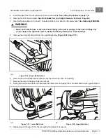
1.
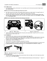
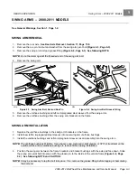
Slide the upright and wheel hub assembly onto the splined half shaft spindle.
See following NOTE.
NOTE:
Apply a small amount of anti-seize compound to the splined front spindle before it is installed.
2.
Loosely secure a large flat washer and new locknut to the spindle.
3.
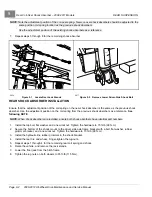
Install the lower ball joint onto the upright lower tab
4.
Install a new locknut, and tighten the hardware to 18 ft-lb (24 N·m).
5.
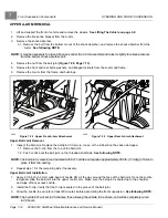
Install the upper ball joint on the upright upper tab
.
6.
Install a new locknut, and tighten the hardware to 18 ft-lb (24 N·m).
7.
Install the drag link ball joint on the tab
.
8.
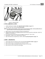
Secure the top end of the shock absorber to the frame with a new flanged bolt and a new locknut. Tighten the
bolt to 73 ft-lb (99 N·m).
9.
Secure the bottom end of the shock absorber to the A-arm with new flanged bolt. Tighten the hardware to
85 ft-lb (115 N·m).
10. Install the caliper assembly on the upright with new lock-patch hex head bolts, and tighten the hardware to 36 ft-lb
(49 N·m).
See Front Brake Pad and Caliper Installation, Section 6, Page 6-7.
11. Install tire and wheel. Finger-tighten lug nuts and lower vehicle.
12. Tighten the lug nuts to 85 ft-lb (115 N·m).
13. Tighten the spindle nut and washer to 150 ft-lb (203 N·m).
14. Align the front wheels, and adjust the toe-in and the camber.
See Wheel Alignment on page 7-10.
Page 7-18
2008-2012 All-Wheel Drive Maintenance and Service Manual
Summary of Contents for Carryall 295 SE
Page 2: ......
Page 20: ......
Page 28: ......
Page 58: ......
Page 66: ......
Page 100: ......
Page 122: ......
Page 150: ......
Page 157: ......
Page 190: ......
Page 197: ......
Page 236: ......
Page 284: ......
Page 386: ......
Page 394: ......
Page 442: ......
Page 452: ......
Page 454: ......
Page 455: ......
Page 456: ......

